Identification of spin wave modes strongly coupled to a co-axial cavity.
Abstract
We demonstrate, at room temperature, the strong coupling of the fundamental and non-uniform magnetostatic modes of an yttrium iron garnet (YIG) ferrimagnetic sphere to the electromagnetic modes of a co-axial cavity. The well-defined field profile within the cavity yields a specific coupling strength for each magnetostatic mode. We experimentally measure the coupling strength for the different magnetostatic modes and, by calculating the expected coupling strengths, are able to identify the modes themselves.
A magnet may be excited in a uniform modeKittel (1947, 1948), where all the constituent moments are precessing in phase, or in non-uniform modesWalker (1957); Fletcher and Bell (1959) where there is a spatially varying phase difference between the moments. The uniform oscillating field that usually drives ferromagnetic resonance excites only the uniform mode or higher order modes with a net dynamic magnetisation. In contrast, if the oscillating field is spatially dependent, perhaps due to the skin depth in the case of a metal ferromagnetKittel (1958); Seavey and Tannenwald (1958) or by design in an electromagnetic waveguide or cavityKhivintsev et al. (2010); Goryachev et al. (2014), then the modes are excited according to the spatial symmetry of the drive field. Such modes are the standing spin waves, and their propagating counterparts are central to the research field of magnonics which introduces the possibility to transfer information over millimeter length scalesEshbach (1962); Tsoi et al. (2000) and perform specific information processing tasksChumak, Serga, and Hillebrands (2014).
Recently there has been a surge of interest in the coupling of magnets to high quality factor electromagnetic cavitiesSoykal and Flatté (2010a, b), motivated by the possibility of performing experiments in quantum magnonics which might allow single localised magnon states to be created and measured. So far, the strong coupling regime of quantum electrodynamics has been reachedZhang et al. (2014); Huebl et al. (2013); Tabuchi et al. (2014); Goryachev et al. (2014) along with demonstrations of magnetically induced transparencyZhang et al. (2014). The strong coupling has been enabled by the high moment density and low magnetic dampingSpencer, Lecraw, and Clogston (1959) in YIG. Both uniform and non-uniform modes have shown strong couplingGoryachev et al. (2014). The work reported in this Letter has been performed in such a context.
We fabricate an easily made cavity (Fig. 1a) with a well-defined non-uniform field specifically so that we can couple into the non-uniform excited modes. It is made from a short ( mm) length of 3.5 mm diameter copper semi-rigid coaxial cable cut flat at each end. These ends are brought into proximity with similarly flat ends in connectorised leads, with a small air gap forming the coupling capacitance. SMA screw connectors provide mechanical stability and allow the size of the air gap, and hence the coupling capacitance, to be varied in a controlled way. At one extreme, the coaxial cables can be brought into contact with each other, transforming the cavity back into a transmission line. We find that the internal quality factor () of our cavity is 515, in close agreement with the theoretical value of calculated from the specified attenuation in the co-axial cable. For the cavity experiments described in this Letter, we tuned the coupling strengths to be MHz, giving a loaded of 261, a fundamental frequency of GHz and a total cavity linewidth of MHz.
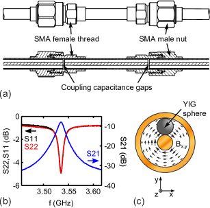
A YIG sphere111Ferrisphere, Inc. of diameter 1 mm is inserted into the cable dielectric at the midpoint of the cavity (Fig. 1c). A key feature of our cavity is the well defined and non-uniform magnetic field profile in the dielectric gap, which has a form in the radial direction. This non-uniform field allows the cavity to couple to both uniform and non-uniform spin-wave modes.
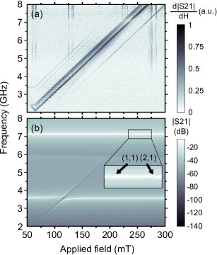
We measure the transmission, S21, of the system using a vector network analyser. The incident power on the cavity is -10 dBm; the driven FMR in this regime is linear, as observed by the independence of S21 on power. We sweep the frequency from 2 GHz to 8 GHz, encompassing both the fundamental mode and the second harmonic of the cavity. A magnetic field is applied parallel to the cavity, and is varied between 50 and 330 mT. In this field range the magnetization of the YIG is fully saturated.
The transmission of the system is shown in Fig. 2. In Fig. 2a we show for the case in which the coupling capacitors are shorted; this is therefore simply transmission line FMR. The magnetostatic band can be clearly seen, comprising a multitude of modes. Unambiguous identification of each one is not trivial; the intensity of each line depends on both the coupling of the magnetostatic mode to the transmission line, and the damping of that modeBilzer et al. (2007), and the linewidth is also dependent on the measurement methodKalarickal et al. (2006).
In Fig 2b we revert to the gap coupled cavity as earlier described. Anticrossings between magnetostatic modes and the cavity resonances at both GHz and GHz are seen, with a maximum coupling strength of 130 MHz for the uniform FMR mode and the fundamental cavity frequency. Coupling to the second harmonic of the cavity is in general much weaker, as the sphere is positioned at a magnetic field node of this cavity mode.
The spatial form and resonant frequencies of modes in magnetized spheres is well knownWalker (1957); Fletcher and Bell (1959). Following WalkerWalker (1957) we label them with indices and 222For some modes, the resonance equation admits more than one solution, which is generally labelled with a third index. As none of the modes we explicitly discuss here have multiple resonances, for simplicity we omit this index.. The radial form of the mode is characterized by , and determines the number of lobes in the mode pattern.
The coupling of the mode to the cavity is given byTabuchi et al. (2014)
Here is the resonance frequency, is the volume of the cavity mode, is the total number of spins in the YIG sphere, is the spin per site, is the permeability of free space and is the relative permitivity of the dielectric within the co-axial cable. The overlap between the cavity mode and the sphere mode () is described by , which is given by
is the r.f. driving field, and is the complex time-dependent off axis sphere magnetization for mode . and are the maximum magnitudes of these, and is the sphere volume. The coupling strength is independent of magnetostatic damping.
The coupling to a particular FMR mode is dependent on the relative symmetries of the mode and the r.f. drive field. It is forced to zero if the mode is antisymmetric with respect to the drive. In particular, for the coupling to the fundamental cavity mode to be significant the FMR mode must be symmetric and low-order in (as the cavity mode is also symmetric). This condition is only met by modes for which . In contrast, in order to couple to the second harmonic cavity mode, the mode must be antisymmetric about . We tabulate calculated coupling constants larger than 1 MHz in Table 1.
| (MHz) | |||
| Fundamental | Second harmonic | ||
| 1 | 1 | 130 | 0 |
| 2 | 1 | 0 | 2.9 |
| 2 | 2 | 27.1 | 0 |
| 3 | 3 | 8.1 | 0 |
| 4 | 4 | 2.8 | 0 |
| 5 | 5 | 1.1 | 0 |
In order to compare these values to our measurement we model the transmission of strongly coupled cavity using the input-output formalismClerk et al. (2010); Zhang et al. (2014); Huebl et al. (2013); Tabuchi et al. (2014). Close to the fundamental mode of the cavity
| S21 | |||
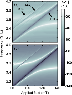
where runs over the magnetostatic modes and are the FMR linewidths. In Fig. 3 we examine the region around the uniform mode’s anticrossing with the cavity fundamental more closely. In Fig. 3a we show the measured transmission, and in Fig. 3b show the calculated transmission over the same range. For modes the two are in good agreement. We attribute the appearance of additional weakly coupled modes to the YIG sphere being slightly off-center in the cavity, which lifts the symmetry conditions described above. This also accounts for the weak coupling of the uniform mode to the second harmonic of the cavity.
In conclusion, we have described a simple tunable cavity-spin ensemble system which can nevertheless achieve the strong coupling limit due to the high spin density in ferrimagnetic YIG. We show that the coupling to the uniform mode is 130 MHz, giving a cooperativity of . Furthermore, the asymmetric but well defined field profile in the cavity permits a quantitative understanding of the coupling to higher order spin wave modes. Coupling between microwave cavities and highly tunable magnonic excitations is a candidate building block for hybrid quantum systems, and the ability to selectively excite specific spin wave modes offers intriguing possibilities in the emerging field of quantum magnonics.
We would like to acknowledge support from Hitachi Cambridge Laboratory, and EPSRC Grant No. EP/K027018/1. A.J.F. is supported by a Hitachi Research fellowship.
References
- Kittel (1947) C. Kittel, “Interpretation of Anomalous Larmor Frequencies in Ferromagnetic Resonance Experiment,” Physical Review 71, 270–271 (1947).
- Kittel (1948) C. Kittel, “On the Theory of Ferromagnetic Resonance Absorption,” Physical Review 73, 155–161 (1948).
- Walker (1957) L. R. Walker, “Magnetostatic Modes in Ferromagnetic Resonance,” Physical Review 105, 390–399 (1957).
- Fletcher and Bell (1959) P. C. Fletcher and R. O. Bell, “Ferrimagnetic Resonance Modes in Spheres,” Journal of Applied Physics 30, 687 (1959).
- Kittel (1958) C. Kittel, “Excitation of Spin Waves in a Ferromagnet by a Uniform rf Field,” Physical Review 110, 1295–1297 (1958).
- Seavey and Tannenwald (1958) M. H. Seavey and P. E. Tannenwald, “Direct observation of spin-wave resonance,” Physical Review 1, 168–169 (1958).
- Khivintsev et al. (2010) Y. V. Khivintsev, L. Reisman, J. Lovejoy, R. Adam, C. M. Schneider, R. E. Camley, and Z. J. Celinski, “Spin wave resonance excitation in ferromagnetic films using planar waveguide structures,” Journal of Applied Physics 108, 023907 (2010).
- Goryachev et al. (2014) M. Goryachev, W. G. Farr, D. L. Creedon, Y. Fan, M. Kostylev, and M. E. Tobar, “High-Cooperativity Cavity QED with Magnons at Microwave Frequencies,” Physical Review Applied 2, 054002 (2014).
- Eshbach (1962) J. R. Eshbach, “Spin-wave propogation and the magnetoelastic interaction in Yttrium Iron Garnet,” Physical Review Letters 8, 357–359 (1962).
- Tsoi et al. (2000) M. Tsoi, A. G. M. Jansen, J. Bass, W. Chiang, V. Tsoi, and P. Wyder, “Generation and detection of phase-coherent current-driven magnons in magetic multilayers,” Nature 406, 46–48 (2000).
- Chumak, Serga, and Hillebrands (2014) A. V. Chumak, A. A. Serga, and B. Hillebrands, “Magnon transistor for all-magnon data processing.” Nature Communications 5, 4700 (2014).
- Soykal and Flatté (2010a) O. O. Soykal and M. E. Flatté, “Strong Field Interactions between a Nanomagnet and a Photonic Cavity,” Physical Review Letters 104, 077202 (2010a).
- Soykal and Flatté (2010b) O. O. Soykal and M. E. Flatté, “Size dependence of strong coupling between nanomagnets and photonic cavities,” Physical Review B 82, 104413 (2010b).
- Zhang et al. (2014) X. Zhang, C.-L. Zou, L. Jiang, and H. X. Tang, “Strongly Coupled Magnons and Cavity Microwave Photons,” Physical Review Letters 113, 156401 (2014).
- Huebl et al. (2013) H. Huebl, C. W. Zollitsch, J. Lotze, F. Hocke, M. Greifenstein, A. Marx, R. Gross, and S. T. B. Goennenwein, “High Cooperativity in Coupled Microwave Resonator Ferrimagnetic Insulator Hybrids,” Physical Review Letters 111, 127003 (2013).
- Tabuchi et al. (2014) Y. Tabuchi, S. Ishino, T. Ishikawa, R. Yamazaki, K. Usami, and Y. Nakamura, “Hybridizing Ferromagnetic Magnons and Microwave Photons in the Quantum Limit,” Physical Review Letters 113, 083603 (2014).
- Spencer, Lecraw, and Clogston (1959) E. G. Spencer, R. C. Lecraw, and A. M. Clogston, “Low-temperature line-width maximum in Yttrium Iron Garnet,” Physical Review Letters 3, 32–33 (1959).
- Note (1) Ferrisphere, Inc.
- Bilzer et al. (2007) C. Bilzer, T. Devolder, P. Crozat, C. Chappert, S. Cardoso, and P. P. Freitas, “Vector network analyzer ferromagnetic resonance of thin films on coplanar waveguides: Comparison of different evaluation methods,” Journal of Applied Physics 101, 074505 (2007).
- Kalarickal et al. (2006) S. S. Kalarickal, P. Krivosik, M. Wu, C. E. Patton, M. L. Schneider, P. Kabos, T. J. Silva, and J. P. Nibarger, “Ferromagnetic resonance linewidth in metallic thin films: Comparison of measurement methods,” Journal of Applied Physics 99, 093909 (2006).
- Note (2) For some modes, the resonance equation admits more than one solution, which is generally labelled with a third index. As none of the modes we explicitly discuss here have multiple resonances, for simplicity we omit this index.
- Clerk et al. (2010) A. A. Clerk, M. H. Devoret, S. M. Girvin, F. Marquardt, and R. J. Schoelkopf, “Introduction to quantum noise, measurement, and amplification,” Reviews of Modern Physics 82, 1155–1208 (2010).