Controlling the Dark Exciton Spin Eigenstates by External Magnetic Field
Abstract
We study the dark exciton’s behavior as a coherent physical two-level spin system (qubit) using an external magnetic field in the Faraday configuration. Our studies are based on polarization-sensitive intensity autocorrelation measurements of the optical transition resulting from the recombination of a spin-blockaded biexciton state, which heralds the dark exciton and its spin state. We demonstrate control over the dark exciton eigenstates without degrading its decoherence time. Our observations agree well with computational predictions based on a master equation model.
Reliable quantum two-level systems (TLS) are the building blocks for quantum information processing (QIP). Solid state quantum bits (qubits) that can also be well-controlled are required for QIP to become a viable technology. An important prerequisite of a solid state qubit is that it has a long coherence time, in which its quantum state is not randomized by spurious interactions with its environment DiVincenzo1995 ; DiVincenzo2000 . Semiconductor quantum dots (QDs) confine charge carriers into a three dimensional nanometer scale region, thus acting in many ways as isolated ’artificial atoms,’ whose properties can be engineered. They are also compatible with modern microelectronics, making them particularly attractive as solid state qubits. Many efforts have been devoted to prepare, control, and measure the quantum states of charge carriers in QDsImamoglu1999 ; PressNat2010 ; GreilichNat2009 ; Kim2010 ; PressNat2008 . One of the more studied TLS in QDs is their fundamental optical excitation, which results in a QD confined electron-hole (e-h) pair. Since light interacts very weakly with the electronic spin, the photogenerated e-h pair has antiparallel spin projections on the incident light directionBenny2011a . Such an e-h pair is called a bright exciton (BE). The coherent properties of the BE have been extensively studied Kodriano2012 ; DeGreveNat2011 ; Godden2012 . The main advantages of the BE qubit are its accessibility to coherent control by light and its neutrality, which results in insensitivity to vicinal electrostatic fluctuations. The main disadvantage is in its short radiative lifetime ( 1 ns). In contrast, dark excitons (DEs) - formed by e-h pairs with parallel spin projections, are almost optically inactive.PoemNat2010 ; Smolenski2012 Due to small BE-DE mixing, induced by the QD deviation from symmetry, DEs may still have some residual optical activity.Zielifniski2015 ; SlavarXiv2016 However, their radiative lifetimes are orders of magnitude longer than that of the BEs Schwartz2015 . DEs, like BEs, are neutral and therefore have a long spin coherence time Schwartz2015 . Recently, it was demonstrated that the DE can be optically initiated in a coherent state by an ultrashort resonant optical pulse Schwartz2015a , and that its quantum state can be coherently controlled and reset using short optical pulses Schwartz2015 ; Schmidgall2015 , making it thus an attractive matter spin qubit.
In this work, we present further experimental study of the DE as a coherent TLS under an external magnetic field and demonstrate full control over its eigenstates. Even at zero magnetic field, due to the short range e-h exchange interaction Poem2007 , the DE spin states are not degenerate. The spin eigenstates are the symmetric and anti-symmetric coherent superpositions of the DE spin up () and spin down () states Bayer2002 . At non-vanishing external magnetic fields, however, when the Zeeman splitting is larger than the exchange interaction, the eigenstates become the and spin states.
Our experimental data is corroborated by a theoretical model which produces excellent agreement with measured photoluminescence (PL) intensity correlations under various magnetic fields and optical excitation intensities. This agreement shows that the externally applied field controls the DE as a qubit, without reducing its inherently long coherence time.
At zero magnetic field, due to the short range e-h exchange interaction, the DE eigenstates are the symmetric and anti-symmetric coherent superposition of the spin up () and spin down () states, where the anti-symmetric state is lower in energy Schwartz2015 . These states are schematically described in Figure.1 The DE can be optically excited, thereby generating a spin blockaded biexciton Kodriano2010 . This biexciton is comprised of two electrons in a singlet configuration at their ground level (total spin projection zero), and two holes with parallel spins forming a triplet (total spin projection ±3), occupying the ground and second hole levels Kodriano2010 . Likewise, as first demonstrated here, the lower and higher eigenstates of the qubit are also the anti-symmetric and symmetric coherent superpositions of the spin up ( ) and spin down ( ), respectively.
The DE and form an optical "-system" since optical transitions are allowed between the () DE state to and from the ( ) biexciton state by right (left) handed circularly polarized light only. At zero magnetic field, the DE and eigenstates are therefore optically connected by linear cross polarized optical transitions denoted as horizontal (H) and vertical (V), where the H direction is chosen such that it coincides with the polarization of the ground state BE optical transition Kodriano2010 . The system is schematically described in Figure.1 (a).
The time independent Hamiltonian of the DE and the in the presence of a magnetic field in the Faraday configuration as expressed in the basis is given by:
| (1) |
This Hamiltonian represents two decoupled Hamiltonians, one for the DE and one for the , where is the Bohr magnetron, B the magnitude of the magnetic field (normal to the sample surface), and are the electron and hole gyromagnetic ratios in the direction of the magnetic field, and is the gyromagnetic ratio of the two heavy holes in triplet configuration. The sign convention for the gyromagnetic factors is such that positive factors mean that electron (heavy hole) with spin parallel (antiparallel) to the magnetic field direction is lower in energy than that with spin antiparallel (parallel) Bayer2002 . We note that the triplet gyromagnetic ratio is not a simple sum of the gyromagnetic ratios of the individual holes Nowak2011 . The energy difference between the DE and the is , and and are the energy differences between the DE and eigenstates, respectively. All energies are defined at zero magnetic field. From this Hamiltonian, one calculates the energies and eigenstates of the system. Figure. 1a schematically describes the DE energy level structure, their magnetic field dependence, and the optical transitions between their eigenstates.
The externally applied magnetic field modifies the eigenstates of both qubits: Bayer2002
| (2) |
where are normalization factors and and are the magnetic energies. The energy difference between the two eigenstates is given by their Zeeman splitting: . If one defines , EQ 2 can be expressed more conveniently as:
| (3) |
Figure. 1b presents an intuitive geometrical interpretation for the angle and the DE Bloch sphere. Since in the Faraday configuration the magnetic field direction is aligned with the direction of the spin state, it follows that is the angle between the Bloch sphere eigenstate axis and the direction of the magnetic field. Thus, as the magnitude of the external field (B) increases approaches and the eigenstates gradually change their nature. Once the Zeeman energies significantly exceed the exchange energies, the eigenstates become the and spin states for the DE and the , respectively.
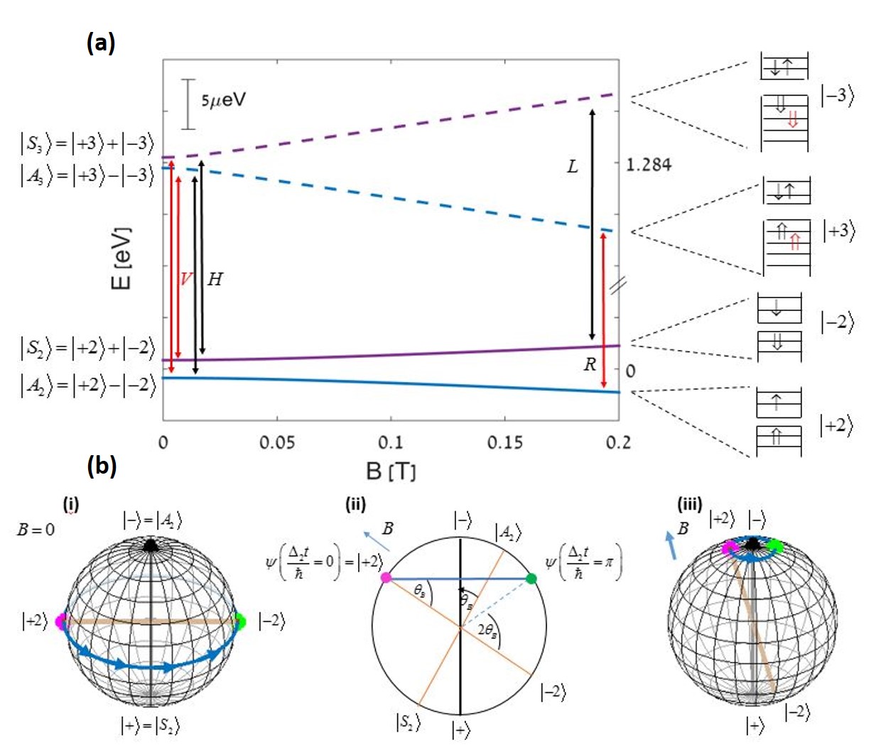
In self assembled InGaAs QDs, the out of plane g-factors of the electron and the heavy hole are known to be both positive Bayer2002 ; Alon-Braitbart2006 with that of the electron larger than that of the hole. As a result the lower energy eigenstate contains an increasing contribution from the spin state while the higher energy contains an increasing contribution from the state, as the magnetic field increases. The behavior of the is similar, because as we show below, the Zeeman splitting of the optical transition from this state to the DE is opposite in sign to the Zeeman splitting of the BE transitions.
As can be seen in Figure 1, at the limit of high magnetic field, the DE - system forms two separate TLSs, in which the DE spin up () and spin down () eigenstates are optically connected to the spin up () and spin down () eigenstates by a right (R) or left (L) hand circularly polarized transition, respectively. The externally applied field thus changes the polarization of the optical transitions between the DE and eigenstates from linearly cross polarized transitions into elliptically –cross- polarized ones as the field increases and eventually the optical transitions become cross-circularly polarized.
The state of a TLS (or a qubit) is conventionally described as a point on the surface of a unit sphere (Bloch sphere). The north pole of the Bloch sphere describes the lower energy eigenstate and the sphere’s south-pole describes the higher energy eigenstate. The surface of the sphere describes all possible coherent superpositions of the TLS eigenstates. Each superposition is therefore uniquely defined by a polar angle () and an azimuthal angle ():
| (4) |
where () is the lower (higher) energy eigenstate at the north (south) pole of the Bloch sphere. When a coherent superposition of a given TLS is formed, the relative phase between the two eigenstates evolves in time, due to the energy difference between the two eigenstates Benny2011a . This evolution can be described as a counter-clockwise precession around an axis connecting the Bloch sphere’s poles at a rate . The evolution is therefore described such that , while remains unchanged as shown in Figure .1b (i), for the case in which a detection of an R circularly polarized - biexciton photon initiated the DE in the coherent state. In this case , and .
The externally applied field, induces changes on the DE and eigenstates as described by EQ. 3. These changes can be described as geometrical "rotations" of their Bloch spheres in space, such that the new direction of the sphere’s axis is given by: where , and are defined above. Thus, there is an angle between the sphere’s axis in the presence of the external field and the axis in the absence of the field, as described in Figure. 1b (ii). Relative to the new axis the qubit spin state evolves in time like
| (5) |
Here, detection of an R polarized - biexciton photon, which initiates the DE in the coherent state, defines that , and . This situation is schematically described in Figure .1b (ii) and (iii).
For probing the DE precession and its dependence on the externally applied magnetic field we used continuous wave (CW) resonant optical excitation of the DE to the -biexciton. In the presence of such a CW resonance light field the two TLSs are coupled and the time independent Hamiltonian is given by
| (6) |
where , is the Rabi frequency for right- R (left – L) hand circularly polarized light. The detuning of the exciting laser energy from the resonant transition between the DE and - biexciton is assumed to be zero in our experiments. EQ. 6 shows that the optical coupling depends on the light polarization and the spin state of the DE. A circularly polarized R (L) photon, is absorbed in proportion to the magnitude of the DE spin state projection on the () state. The -biexciton then starts to precess while it radiatively recombines into an excited DE state. Detection of a right (left) hand circularly polarized photon heralds the system in a well-defined DE state given by (). The DE then precesses until a second photon is absorbed, and the process repeats itself. Therefore, time resolved intensity autocorrelation measurements of the spectral line in the circularly polarized basis, provide a straightforward experimental way for probing the dynamics of the system Schwartz2015 . In the absence of an external field and at low resonant excitation intensities, such measurements show a temporally oscillating signal at the frequency . The visibility of the oscillations in the degree of circular polarization can be used as a measure for (where is the time of detecting the first polarized photon), and the phase of the signal as a measure for Schwartz2015a .
Our experiments used QDs grown by molecular beam epitaxy (MBE) on a [001]-oriented GaAs substrate. One layer of self-assembled InGaAs QDs was deposited in the center of a one-wavelength microcavity sandwiched between an upper and lower set of AlAs/GaAs quarter-wavelength layer Bragg mirrors. The sample was placed inside a tube, immersed in liquid helium, maintaining a temperature of K. Conducting coil outside the tube was used for generating an external magnetic field along the tube axis, permitting this way optical studies in Faraday configuration. A x60, 0.85 numerical aperture microscope objective was used to focus the excitation lasers on the sample surface and to collect the emitted light. We used low intensity high above bandgap energy 445nm diode CW laser light to photogenerate a steady state population of DEs in the QD in a statistical manner Nguyen2012 . In addition, by using a grating stabilized tunable CW diode laser, we resonantly excited the DE population in one of the QDs into a population Schwartz2015 .
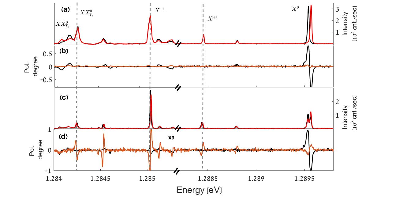
Figure 2 shows polarization sensitive PL spectra of the single QD under study. The PL was excited using 445nm non-resonant cw laser light. Figure 2a (2c) presents the measured spectra in the two linear (circular) polarizations, in the absence (presence of T) external magnetic field. Figure 2b (2d) presents the obtained degrees of linear (circular) polarizations as a function of the emitted photon energy in the absence (presence of T) external magnetic field. In Figure. 2a the solid black (red) line represents horizontal - H (vertical - V) polarization and in Figure 2c black (red) line represents left- L (right-R) hand circular polarization. Black (orange) lines in Figure 2b and 2d represent the degree of linear (circular) polarization. The various exciton and biexciton lines are identified in Figure 2a.
Even in the absence of a magnetic field, one can clearly observe in Figure 2a and 2b that the BE spectral line is split into two cross linearly polarized components. This split, measured to be eV is common to self assembled QDs. It results from the anisotropic e-h exchange interaction, mainly due to the QD deviation from cylindrical symmetry. Bayer2002 ; Ivchenko2012 The DE degeneracy is also removed mainly due to the short range e-h exchange interaction Bayer2002 ; Ivchenko2012 . However, since the splits and are smaller than the radiative linewidth, the linearly polarized components of the biexciton line cannot be spectrally resolved. Therefore, only one, unpolarized spectral line is observed. An upper bound for < corresponding to split of less than eV is deduced directly from the degree of circular polarization memory of the biexciton line at zero magnetic field Schwartz2015 . At a sufficiently large magnetic field the line splits into two components. The lower energy transition is R-circularly polarized and the upper energy one is L-circularly polarized. At a magnitude of T, the splitting amounts to eV and it exceeds the measured linewidth of eV in the absence of external field.
We note that the measured Zeeman splitting of the line is opposite in sign to those of the , the , and the excitonic lines. It follows from simple considerations that the expected Zeeman splitting of the charged and neutral excitonic spectral lines is proportional to the sum of the hole and electron g-factors . Therefore the R polarized part of these spectral lines is expected to be higher in energy than the L polarized part. This is indeed what we experimentally observe. Since the line splits in proportion to our experimental observations indicate that the sign of is negative, and its magnitude in this particular QD is larger than that of the electron g-factor. These observations are in agreement with the energy level diagram of Figure. 1a. The dependences of the Zeeman splitting of the various spectral lines on the g-factors are summarized in Table 1.
| Line | Zeeman Splitting | Measured at T in (eV) |
|---|---|---|
In order to probe the precession of the DE, we excite the sample with low intensity 445 nm CW laser light. This non-resonant excitation photogenerates the QD confined BE and DE in a statistical manner. The BE recombines radiatively within about 1ns, while the DE remains in the QD until it decays radiatively or an additional charge carrier enters the QD, whichever comes first. The rate by which additional carriers enter depends linearly on the power of the (blue) laser light (). One can tune such that the average time between consecutive arrivals of carriers to the QD is comparable to the radiative lifetime of the DE. Schwartz2015 An additional circularly polarized CW laser light, resonantly tuned to the DE- transition is then used for probing the DE precession Benny2011 .
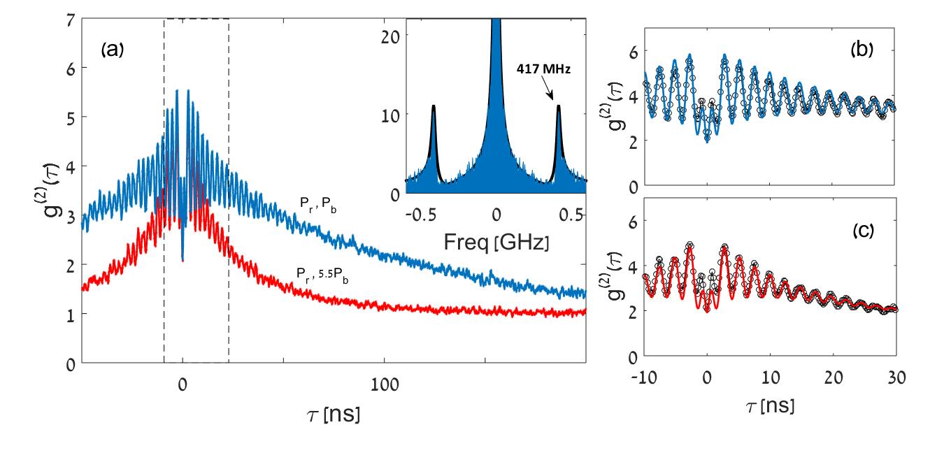
In Figure 3(a-c), we present measured and fitted intensity autocorrelation functions at zero applied magnetic field. As defined, the functions are normalized to unity at . Two measurements in two vastly different powers of the blue laser are presented together in Figure 3(a) to clearly demonstrate the reduction of the DE lifetime resulting from the increase in the non-resonant excitation power. The DE lifetime decreases significantly as the non-resonant blue light () power increases as a result of the increase in the flux of carriers accumulating in the QD. All other experimental conditions, in particular the intensity of the resonant laser (), were kept the same. The measured data points (dots) are overlaid by our model best fits (continuous lines in Figure 3(b,c)) using the parameters listed in Table 2 convoluted with the system temporal response function PoemNat2010 . The temporal oscillations in the correlation function resulting from the precession of the DE Schwartz2015 , are clearly observed as well. The inset to Figure 3(a) shows the Fourier transform of the measured and calculated correlation functions under weak blue excitation. From these measurements we calculate a precession frequency of MHz, which corresponds to a precession period of ns and a natural splitting of μeV between the two DE eigenstates. This splitting, in the absence of magnetic field is due to the short-range e-h exchange interaction Bayer2002 ; Zielifniski2015 . The measured full width at half maximum of the DE frequency at this intensity is MHz and it increases with the excitation power of both the blue and red laser. This power induced broadening is a consequence of the polarization oscillation decay, induced by the resonant CW excitation. Much longer polarization decay times are measured under pulsed excitation Schwartz2015 .
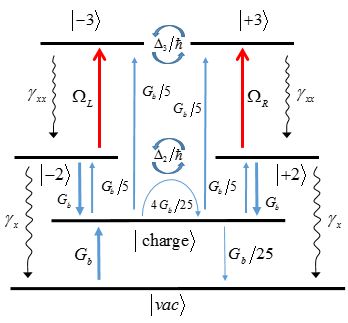
To model our measurements, we added to the Hamiltonian presented in Eq 6 a vacuum state and a charge state as shown in Figure 4, which schematically describes the various states of the system and the transition rates between these states. For the sake of simplicity, we only included one additional auxiliary charged state in our model. This charge level represents all states which do not participate in the optical transitions, such as a singly positive or negative charged QD. With this degree of simplicity, however, we had to estimate the various proportionality constants to by which the charged state is connected to other states by the blue laser excitation (see Figure 4). These non-resonant optical charging and discharging rates, marked by upward and downwards vertical blue arrows are proportional to the non resonant excitation rate . They were deduced from a set of power dependent measurements at zero magnetic field. The various rates used in our model are defined in Table 2.
We then solved the system’s master equation, which includes a Lindblad dissipation part in addition to the Hamiltonian
| (7) |
where represents the various non-Hermitian dissipation rates. The various parameters used as input to the model are listed and referenced in Table 2. in Figure 4 represents the rate by which electrons and holes are equally added non coherently to the QD by the non-resonant blue laser excitation and it is therefore proportional to the power of blue laser (). Since the DE radiative lifetime is very long, essentially defines the DE lifetime, and the probability to find a DE in the QD. Therefore can be deduced directly from the decay of the autocorrelation measurements to its steady state (see Figure 3). Likewise was set proportional to the square root of the R (L) circularly polarized red laser power , as deduced from the power needed to saturate the PL under excitation with this source. At saturation the co (cross)-circular intensity autocorrelation signal exhibits no oscillations, while the lower the power is, the more oscillations are observed. This feature facilitated quite sensitive fitting of so that the observed and calculated number of oscillations match.
We use the quantum regression theorem Loudon2000 to solve the master equation and thus to describe the temporal evolution of the system. From the numerical solution, we calculated the polarization sensitive intensity autocorrelation measurement of the line, where detection of the first photon sets the initial system conditions, and the time by which the second photon is detected defines the time by which the system evolution is calculated Regelman2001 . The calculations were repeated for various blue light and resonance excitation intensities, and as a function of the magnitude of the externally applied magnetic field.
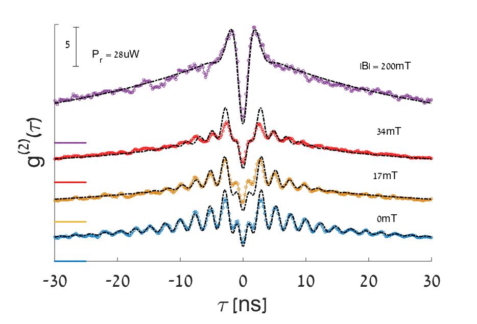
Figure 5 shows co-circular polarization sensitive intensity autocorrelation measurements of the emission from the biexciton line under weak non-resonant () and resonant () excitation powers, for various externally applied magnetic fields. Here as well, the measured data points (dots) are overlaid by our model simulations (dashed lines), convoluted by the detectors temporal response.
| Parameter | Symbol | Value | Unit | Obtained by |
|---|---|---|---|---|
| lifetime | nsec | Measured | ||
| DE lifetime | nsec | Measured | ||
| precession rate | rad/nsec | Measured lower bound | ||
| DE precession rate | rad/nsec | Measured | ||
| Electron g-factor | dimensionless | Measured from different dot. | ||
| Hole g-factor | dimensionless | Measured from different dot. | ||
| Triplet hole g-factor | dimensionless | Measured Zeeman splitting |
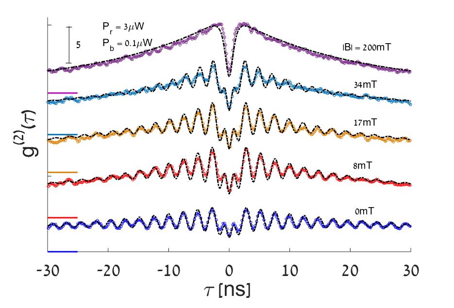
The specific DE-biexciton resonance that we discussed so far is such that an electron is added to the first level and a heavy hole is added to the second level thereby directly exciting the biexciton. The use of this resonance is not very convenient for two reasons: a) The oscillator strength of the resonance is relatively weak due to the different parities of the electron and heavy-hole envelope functions. b) The width of this resonance is relatively narrow, since it is set by the radiative recombination lifetime of the state ( ps). As a result, excitation to this resonant is very sensitive to the detuning from resonance, which becomes highly sensitive to the externally applied magnetic field. We therefore repeated the measurements using a DE-biexciton resonance in which, as before, the electron is added to the first level but the heavy hole is added to the fourth level. This excited biexciton state has significantly larger oscillator strength, since the electron and hole envelope wavefunctions are of same parity. Moreover, this excited biexciton state relaxes non-radiatively, by a spin conserving process in which a phonon is emitted, to the ground state. The process occurs within ps (see Supplementary Information of Ref 12). As a result, the width of the resonance is significantly broader than that of the , and consequently its excitation is less sensitive to detuning and to variations in the externally applied field. These advantages, make the experiments less demanding, while hardly affecting our conclusions regarding the influence of the externally applied field on the DE as a qubit.
Figure 6 shows, co-circular polarization sensitive intensity autocorrelation measurements of the emission line for various magnetic field intensities, under fixed weak non-resonant () and quasi-resonant () excitation powers. The measured data points (dots) are overlaid by our model simulations (dashed lines). For these simulations the excited biexciton levels were added to the model, together with their non-radiative, spin preserving relaxation channels. The observed reduction in the visibility of the oscillations as the magnetic field increases is observed in both resonant and quasi-resonant excitations. The source of this reduction is explained in Figure 1(b) as resulting from the field induced changes in the DE qubit eigenstates. For example, at a field of T the DE splitting was calculated in Figure 1 to be µeV, which is larger than the measured zero magnetic field splitting of µeV. Hence, as expected, no oscillations are observed, and the system can be described as two separated TLSs.
In Figure 7(a), we present as an example, the measured (points) and best fitted model calculations (convoluted with the detector response, solid lines) polarization sensitive intensity auto correlation functions of the line at mT for the quasi-resonant excitation case. The blue (red) color represents co- (cross-) circular polarizations of the first and second detected photon. From the two autocorrelation functions and , the temporal response of the degree of circular polarization (DCP) can be readily obtained:
| (8) |
In Figure 7(b), we present , obtained from Figure 7(a), where data points present the measured value and the orange dashed line represents the DCP obtained from the best fitted numerical model without convolving the detector response function.
The DCP can be also obtained analytically, using the following considerations: Recalling that the DCP is given by:
| (9) |
and substituting using Eq 3 and Eq 5 one obtains:
| (10) |
Eq 10 describes the temporal evolution of the DCP assuming that the first detected photon is R polarized ( in Eq 3 ), the radiative decay is instantaneous, and the coherence of the DE is infinitely long. The fact that the biexciton precesses and has a finite radiative lifetime () adds a prefactor to Eq 10. This prefactor was deduced directly from the polarization memory measurements. Assuming, in addition, that the DCP decays exponentially with a characteristic time , due to the optical re-excitation and the decoherence of the DE, transforms Eq 10 into:
| (11) |
From Eq 11 the visibility of the DCP oscillations and its dependence on the magnetic field can be straightforwardly calculated for the case :
| (12) |
where and are obtained from Eq 11 for and , respectively, and , includes corrections due to the exponential decay of the DCP.
The best fitted numerical model to the data of each of the measurements, presented in Figure 6, represents the measured evolution of the DE after the quantified finite temporal response of the experimental setup was considered. Therefore, to the best numerical model fits, those without the convoluted spectral response of the system, we fitted the analytical expression of Eq 11, as shown in Figure 7 (b) by the dashed black line.
The observed decay of the DCP () has two main contributions. The first one results from the actual decoherence of the DE spin qubit due to its interaction with the nuclei spins . The second one results from the spontaneous nature of the radiative recombination and its re-excitation using CW light field. In order to estimate , the second contribution should be reduced to minimum. Using weak pulsed excitation rather than CW, we previously showed that the coherence time of the DE has a lower bound of about 100 nsSchwartz2015 .
The obtained visibilities and DCP decay times are summarized in the upper and lower insets to Figure 7(b), respectively. As expected, the increase in the magnetic field does not affect the coherence of the DE as clearly seen in the lower inset to Figure 7(b). Clearly, the decay of the DCP () is almost field independent. Moreover, since the obtained of about ns is about an order of magnitude shorter than that measured under pulsed excitation in Ref [16], one can safely deduce that the dominant mechanism, which defines the DCP oscillations decay time in our measurements is the resonantly exciting laser field.
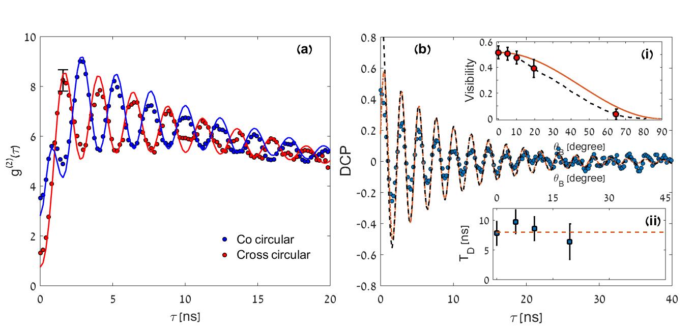
In contrast, the upper inset to Figure 7(b) shows that the visibility of the DCP oscillations depends on the externally applied field. This dependence is readily understood from Figure 1(b.ii) and Eqs. 11 and 12, as resulting from the magnetic field induced changes of the eigenstates of the DE qubit. Symbols in the upper inset represent the measured visibility (derived from the first valley and second peak of the modeled DCP). The expected dependence from the numerical model is represented by a dash black line and that expected from Eq. 12 is represented by a solid orange line. The slight difference between the full numerical model and the simple analytical one is the absence of the effect of other levels (such as the DE biexciton) in the analytical model.
In summary, we present an experimental and theoretical study of the quantum dot confined dark exciton as a coherent two level system subject to an externally applied magnetic field. Experimentally, we used polarization sensitive intensity autocorrelation measurements of the optical transition which connect a biexciton state with the dark exciton state. Detection of a circularly polarized photon from this transition heralds the dark exciton and its spin state. By applying an external magnetic field in the Faraday configuration, we measured the Zeeman splitting of various lines and accounted for our measurements by determining the g-factors of the electron, the hole and that of two holes in a triplet spin state. We then used the external field as a tuning knob for varying the dark exciton eigenstates. We showed that this external control knob does not affect the long coherence time of the dark exciton. Theoretically, we were able to describe all our measurements using a Lindblad type master equation model with a minimal number of free fitting parameters. Ultimately, our work provides a better understanding of the fundamentals of quantum dot excitations and may enable their use in future technologies.
The support of the U.S. Israel Binational Science Foundation (BSF), the Israeli Science Foundation (ISF), The Lady Davis Fellowship Trust and the Israeli Nanotechnology Focal Technology Area on “Nanophotonics for Detection” are gratefully acknowledged.
References
- [1] David P. DiVincenzo. Quantum computation. Science, 270(5234):255–261, 1995.
- [2] David P. DiVincenzo. The physical implementation of quantum computation. Fortschritte der Physik, 48(9-11):771–783, 2000.
- [3] A. Imamoglu, D. D. Awschalom, G. Burkard, D. P. DiVincenzo, D. Loss, M. Sherwin, and A. Small. Quantum information processing using quantum dot spins and cavity qed. Phys. Rev. Lett., 83:4204–4207, Nov 1999.
- [4] Kristiaan Press, David andDe Greve, Peter L. McMahon, Thaddeus D. Ladd, Benedikt Friess, Christian Schneider, Martin Kamp, Sven Hofling, and Yamamoto Yoshihisa Forchel, Alfred. Ultrafast optical spin echo in a single quantum dot. Nat Photon, 6:993–997, Jun 2010.
- [5] A. Greilich, Sophia E. Economou, S. Spatzek, D. R. Yakovlev, D. Reuter, A. D. Wieck, T. L. Reinecke, and M. Bayer. Ultrafast optical rotations of electron spins in quantum dots. Nat Phys, 5:993–997, Apr 2009.
- [6] Erik D. Kim, Katherine Truex, Xiaodong Xu, Bo Sun, D. G. Steel, A. S. Bracker, D. Gammon, and L. J. Sham. Fast spin rotations by optically controlled geometric phases in a charge-tunable inas quantum dot. Phys. Rev. Lett., 104:167401, Apr 2010.
- [7] David Press, Thaddeus D. Ladd, Bingyang Zhang, and Yoshihisa Yamamoto. Complete quantum control of a single quantum dot spin using ultrafast optical pulses. Nature, 456(7219):218–221, November 2008.
- [8] Y. Benny, S. Khatsevich, Y. Kodriano, E. Poem, R. Presman, D. Galushko, P. M. Petroff, and D. Gershoni. Coherent optical writing and reading of the exciton spin state in single quantum dots. Phys. Rev. Lett., 106:040504, Jan 2011.
- [9] Y. Kodriano, I. Schwartz, E. Poem, Y. Benny, R. Presman, T. A. Truong, P. M. Petroff, and D. Gershoni. Complete control of a matter qubit using a single picosecond laser pulse. Phys. Rev. B, 85:241304, Jun 2012.
- [10] Kristiaan De Greve, Peter L. McMahon, David Press, Thaddeus D. Ladd, Dirk Bisping, Christian Schneider, Martin Kamp, Lukas Worschech, Sven Hofling, Alfred Forchel, and Yoshihisa Yamamoto. Ultrafast coherent control and suppressed nuclear feedback of a single quantum dot hole qubit. Nat Phys, 7(11):872–878, November 2011.
- [11] T. M. Godden, J. H. Quilter, A. J. Ramsay, Yanwen Wu, P. Brereton, S. J. Boyle, I. J. Luxmoore, J. Puebla-Nunez, A. M. Fox, and M. S. Skolnick. Coherent optical control of the spin of a single hole in an inas/gaas quantum dot. Phys. Rev. Lett., 108:017402, Jan 2012.
- [12] E. Poem, Y. Kodriano, C. Tradonsky, N. H. Lindner, B. D. Gerardot, P. M. Petroff, and D. Gershoni. Accessing the dark exciton with light. Nat Phys, 6:993–997, Dec 2010.
- [13] T. Smolenski, T. Kazimierczuk, M. Goryca, T. Jakubczyk, L. Kopotowski, L. Cywinski, P. Wojnar, A. Golnik, and P. Kossacki. In-plane radiative recombination channel of a dark exciton in self-assembled quantum dots. Phys. Rev. B, 86:241305, Dec 2012.
- [14] M. Zieliński, Y. Don, and D. Gershoni. Atomistic theory of dark excitons in self-assembled quantum dots of reduced symmetry. Phys. Rev. B, 91:085403, Feb 2015.
- [15] Y. Don, M. Zieliński, and D. Gershoni. The optical activity of the dark exciton. (unpublished, arXiv, 1601.05530), Jan 2016.
- [16] I. Schwartz, E. R. Schmidgall, L. Gantz, D. Cogan, E. Bordo, Y. Don, M. Zielinski, and D. Gershoni. Deterministic writing and control of the dark exciton spin using single short optical pulses. Phys. Rev. X, 5:011009, Jan 2015.
- [17] I. Schwartz, D. Cogan, E. R. Schmidgall, L. Gantz, Y. Don, M. Zieliński, and D. Gershoni. Deterministic coherent writing of a long-lived semiconductor spin qubit using one ultrafast optical pulse. Phys. Rev. B, 92:201201, Nov 2015.
- [18] E. R. Schmidgall, I. Schwartz, D. Cogan, L. Gantz, T. Heindel, S. Reitzenstein, and D. Gershoni. All-optical depletion of dark excitons from a semiconductor quantum dot. Applied Physics Letters, 106(19), 2015.
- [19] E. Poem, J. Shemesh, I. Marderfeld, D. Galushko, N. Akopian, D. Gershoni, B. D. Gerardot, A. Badolato, and P. M. Petroff. Polarization sensitive spectroscopy of charged quantum dots. Phys. Rev. B, 76:235304, Dec 2007.
- [20] M. Bayer, G. Ortner, O. Stern, A. Kuther, A. A. Gorbunov, A. Forchel, P. Hawrylak, S. Fafard, K. Hinzer, T. L. Reinecke, S. N. Walck, J. P. Reithmaier, F. Klopf, and F. Schäfer. Fine structure of neutral and charged excitons in self-assembled in(ga)as/(al)gaas quantum dots. Phys. Rev. B, 65:195315, May 2002.
- [21] Y. Kodriano, E. Poem, N. H. Lindner, C. Tradonsky, B. D. Gerardot, P. M. Petroff, J. E. Avron, and D. Gershoni. Radiative cascade from quantum dot metastable spin-blockaded biexciton. Phys. Rev. B, 82:155329, Oct 2010.
- [22] M. P. Nowak and B. Szafran. Singlet-triplet avoided crossings and effective factor versus spatial orientation of spin-orbit-coupled quantum dots. Phys. Rev. B, 83:035315, Jan 2011.
- [23] S. Alon-Braitbart, E. Poem, L. Fradkin, N. Akopian, S. Vilan, E. Lifshitz, E. Ehrenfreund, D. Gershoni, B.D. Gerardot, A. Badolato, and P.M. Petroff. Magneto optics of single photons emitted from single inas/gaas self-assembled quantum dots in a planar microcavity. Physica E: Low-dimensional Systems and Nanostructures, 32(12):127 – 130, 2006. Proceedings of the 12th International Conference on Modulated Semiconductor StructuresProceedings of the 12th International Conference on Modulated Semiconductor Structures.
- [24] H. S. Nguyen, G. Sallen, C. Voisin, Ph. Roussignol, C. Diederichs, and G. Cassabois. Optically gated resonant emission of single quantum dots. Phys. Rev. Lett., 108:057401, Jan 2012.
- [25] E.L. Ivchenko and G. Pikus. Superlattices and Other Heterostructures: Symmetry and Optical Phenomena. Springer Series in Solid-State Sciences. Springer Berlin Heidelberg, 2012.
- [26] Y. Benny, Y. Kodriano, E. Poem, S. Khatsevitch, D. Gershoni, and P. M. Petroff. Two-photon photoluminescence excitation spectroscopy of single quantum dots. Phys. Rev. B, 84:075473, Aug 2011.
- [27] Rodney Loudon. The quantum theory of light. Oxford university press, 2000.
- [28] D. V. Regelman, U. Mizrahi, D. Gershoni, E. Ehrenfreund, W. V. Schoenfeld, and P. M. Petroff. Semiconductor quantum dot: A quantum light source of multicolor photons with tunable statistics. Phys. Rev. Lett., 87:257401, Nov 2001.