Manipulation of magnetic Skyrmions with a Scanning Tunneling Microscope
Abstract
The dynamics of a single magnetic Skyrmion in an atomic spin system under the influence of Scanning Tunneling Microscope is investigated by computer simulations solving the Landau-Lifshitz-Gilbert equation. Two possible scenarios are described: manipulation with aid of a spin-polarized tunneling current and by an electric field created by the scanning tunneling microscope. The dynamics during the creation and annihilation process is studied and the possibility to move single Skyrmions is showed.
pacs:
75.78.-n, 75.10.Jm, 75.10.HkMagnetic Skyrmions have been intensively studied during the last period of time due to the possibility to use them as potential candidates for data storage Zhang et al. (2015a); Zhou and Ezawa (2014); Fert et al. (2013), for logic devices Zhang et al. (2015b), or as Skyrmion transistor Zhang et al. (2015c). The idea to use local changes in the magnetic structure is not new: Bubble domains in thin film structures O’Dell (1986), magnetic domain walls in nanowires driven by an electric current Parkin et al. (2008), and magnetic vortices Wieser et al. (2006); Yamada et al. (2007) have been considered as candidates for data storage and / or logic devices. However, due to the stability as result of their topology (topological protected) and their dimension (just a view nanometer) magnetic Skyrmions are promising candidates for future spintronic devices.
Furthermore, magnetic Skyrmions can be found in thin film systems on the microscopic Jiang et al. (2015); Woo et al. (2016); Mühlbauer et al. (2009) but also on the atomic length scale Romming et al. (2013); Barker and Tretiakov (2016). In the moment most of the focus lies on the magnetic Skyrmions at the microscopic length scale. The reason can be found in the possibility to observe these Skyrmions at room temperature and with several experimental techniques like e.g. magnetic transmission X-ray microscopy Woo et al. (2016) or magneto-optical Kerr effect microscopy Jiang et al. (2015); Lin (2016). For Skyrmions at the atomic length scale this is not the case. Here, a scanning tunneling microscope and low temperatures ( K) are necessary. On the other hand the technological goal is to reduce the size which is needed to store information. Therefore, magnetic Skyrmions on the atomic length scale can be seen as the next step after realizing Skyrmion devices on the microscopic scale.
The first step toward this direction has been already done. Recent experiments have shown that it is possible to switch magnetic Skyrmions on the atomic length scale with aid of a scanning tunneling microscope (STM) Romming et al. (2013); Hsu et al. (2016). Within these publications two different methods to manipulate the Skyrmion have been demonstrated: 1. creating and annihilating Skyrmions with spin-polarized tunnel currents and 2. using electric fields. While for the first experiment a magnetized STM tip is needed this is not the case for the switching process using electric fields. Therefore, the manipulation using electric fields is preferable. However, the problematic point in both experimental situations is the time resolution. The time resolution of a conventional scanning tunneling microscope is not high enough to investigate the dynamics during the experiment. Therefore, spin dynamics simulations are a perfect way to investigate the dynamics and to get deeper insights in the physics of Skyrmions.
The theoretical publications Hagemeister et al. (2015); Siemens et al. (2016) discuss the ground state configuration, the energy barrier between the ferromagnetic and the Skyrmion state and give an idea about the dynamics. However, these publications don’t describe the creation or annihilation processes using spin-polarized tunneling currents or electric fields. These informations will be given in this Letter which provides a description of the switching dynamics using STM in both cases spin-polarized with tunneling currents and not spin-polarized using electric fields. Furthermore, the possibility to move a single Skyrmion with aid of an STM and without disturbing surrounding Skyrmions will be demonstrated.
The Manuscript is organized as follow: After introducing the investigated system as well as the corresponding equation of motion the Landau-Lifshitz-Gilbert equation with additional spin torque terms, the dynamics during the creation and annihilation process will be described and the possibility to move a single Skyrmion with an STM demonstrated. Thereby, both experimental ways: the usage of a spin-polarized tunneling current as well as the an electric field are considered. The Letter ends with a summary.
The investigated system is a spin system on the atomic length scale with a triangular lattice similar to the double layer Pd/Fe on Ir(111) described in Hagemeister et al. (2015). The lateral dimension of the film is nm 45.6 nm (39204 spins) and the magnetic properties of the system are well described by the following Hamiltonian:
The first two terms are the ferromagnetic exchange and Dzyaloshinky-Moriya interaction (DMI) where mev and meV have been assumed. The Dzyaloshinky-Moriya vectors are oriented in-plane (film plane) perpendicular to the lattice vector pointing from lattice site to . The third term describes the influence of an external magnetic field perpendicular to the film plane in -direction.
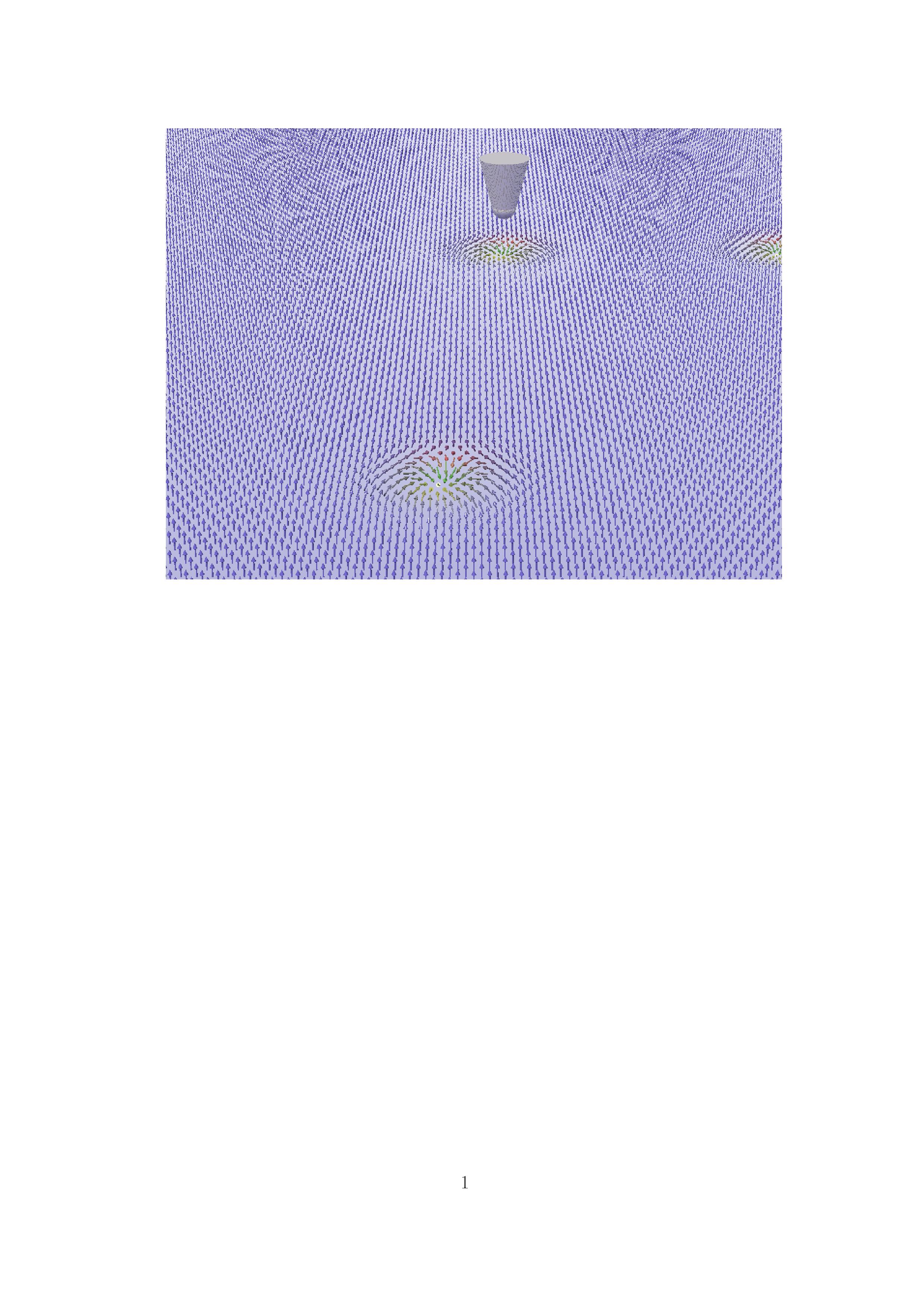
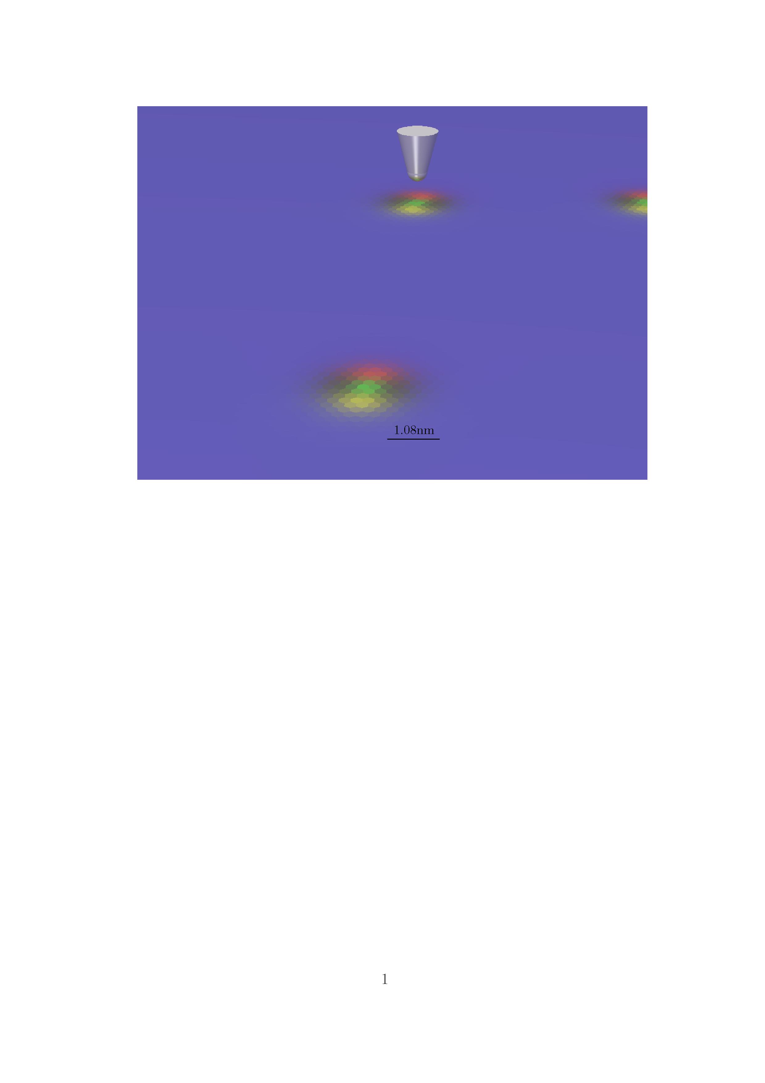
Without magnetic field T the system shows a maze like spin spiral structure Hagemeister et al. (2015). With external field the magnetic configuration provides Merons Ezawa (2011) and at larger fields ( approximately in between 4 and 10 T) Skyrmions which due to the in plane orientation of show a hedgehog structure with magnetic moments pointing to the center of the Skyrmion. For T the ferromagnetic state is the ground state and Skyrmions are no longer existent. The Skyrmionic structure as well as the color coding of the pictures are given in Fig. 1. All figures have the same camera position and therefore the same color coding even if the focus varies. The diameter of the Skyrmion depends on the strength of the external field. During the simulations T (Skyrmion creation and destruction) and T (manipulation) have been used. Therefore, the corresponding Skyrmion diameter are nm (T) and nm (T).
The dynamics of the system is described by the Landau-Lifshitz-Gilbert (LLG) equation with additional spin transfer torques:
The first and second term are the precessional and relaxation term of the conventional LLG equation with the effective field: , where is a white noise which simulates the effect of temperature. For the description of the manipulation via electric fields underneath the tip (radius nm) a locally increased temperature: K (Joule heating) has been taken into account. During the simulations describing the manipulation using spin-polarized tunnel currents no temperature effects have been taken into account. The other parameters in the LLG equation are the gyromagnetic ratio , the magnetic moment in Bohr magneton , and the dimensionless Gilbert damping constant . The third and fourth term are spin transfer torques describing the influence of an spin polarized current. These terms have been modified to describe the tunnel current of a spin-polarized scanning tunneling microscope: and have been assumed. The model which describes the local strength of the current is the Tersoff-Hamann model which leads to:
where is the polarization of the tip, the strength of the current, 1/m is related to the work function of the tip and is the tip position which is time dependent, and the position vector within the lattice.
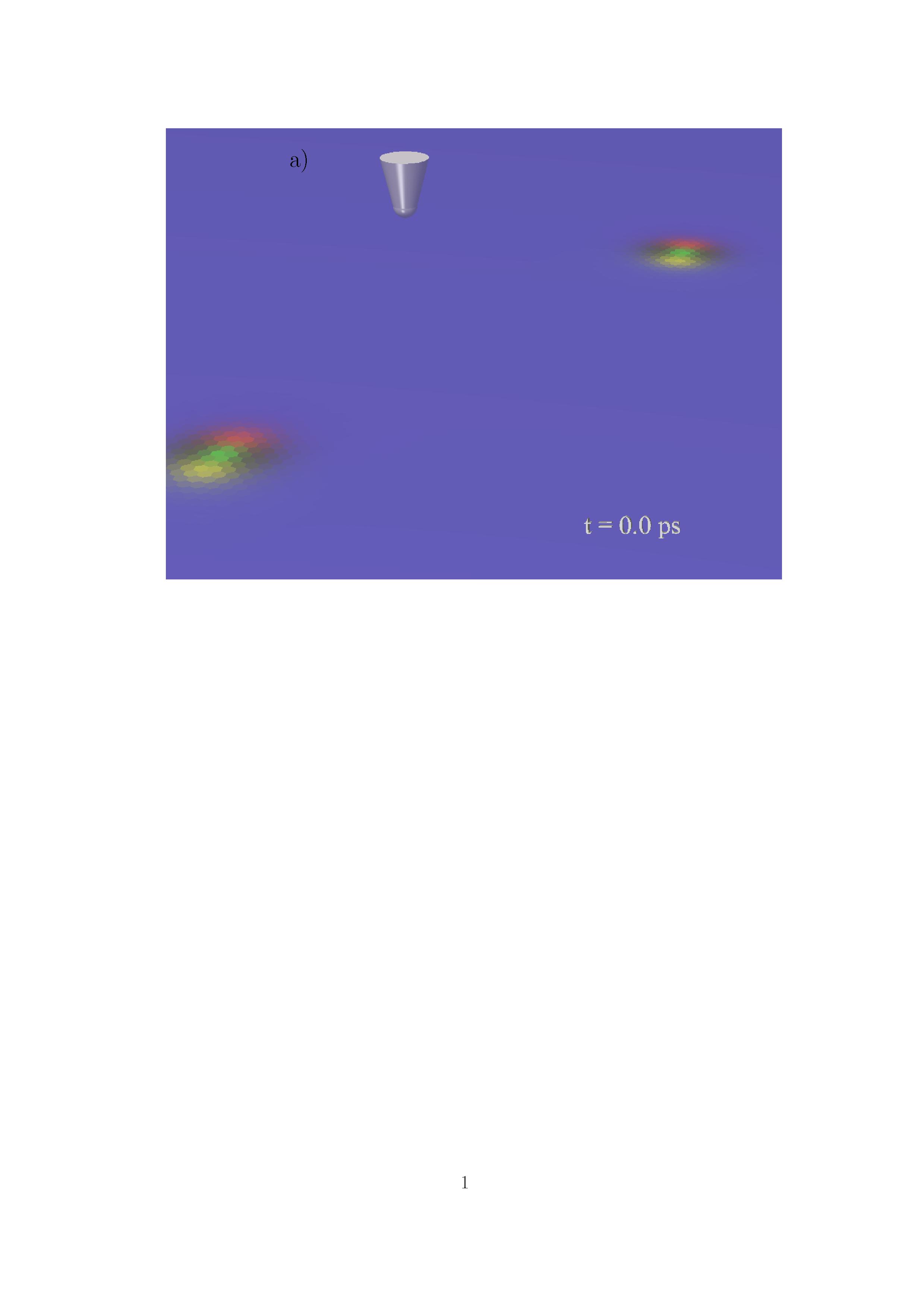
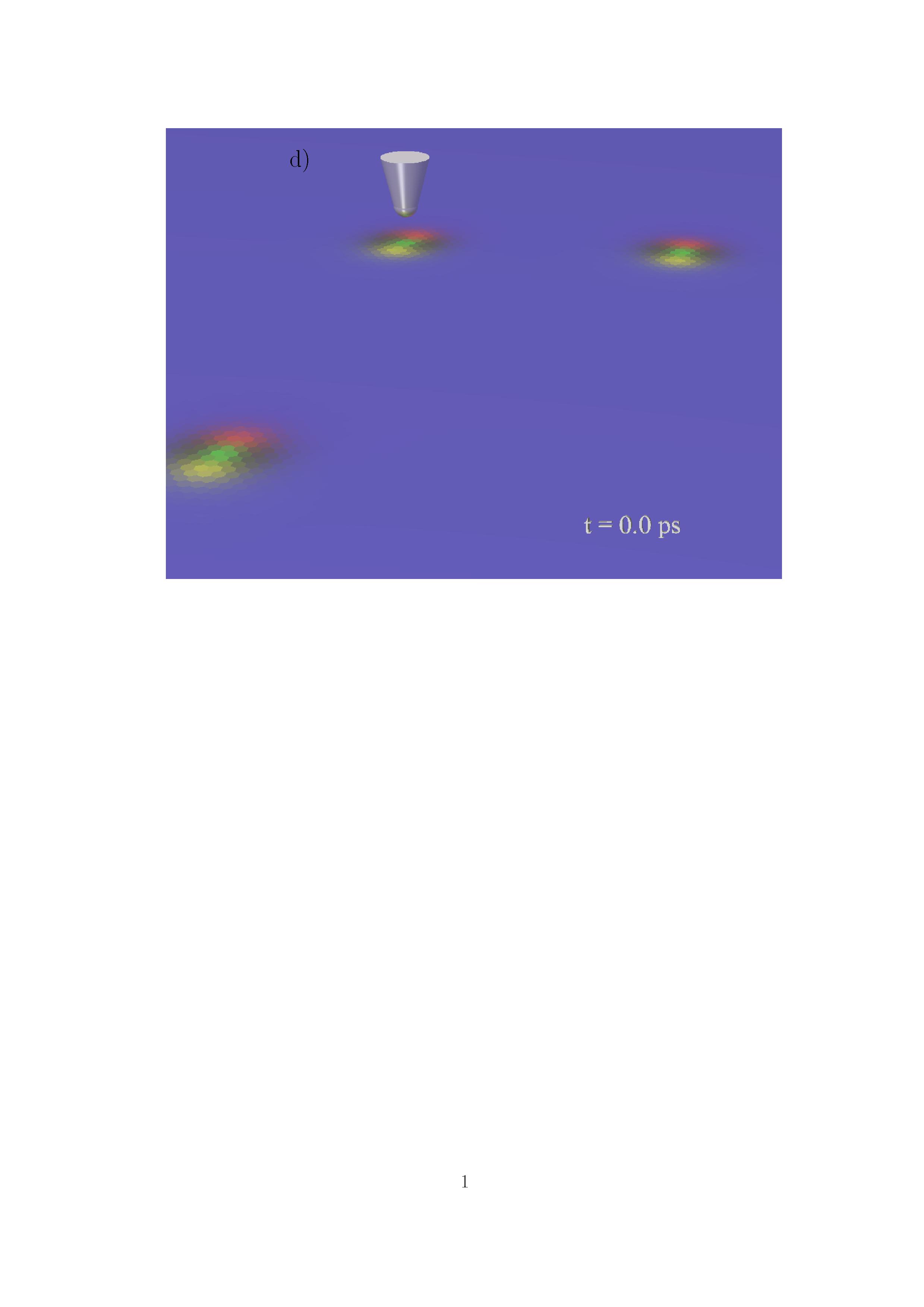
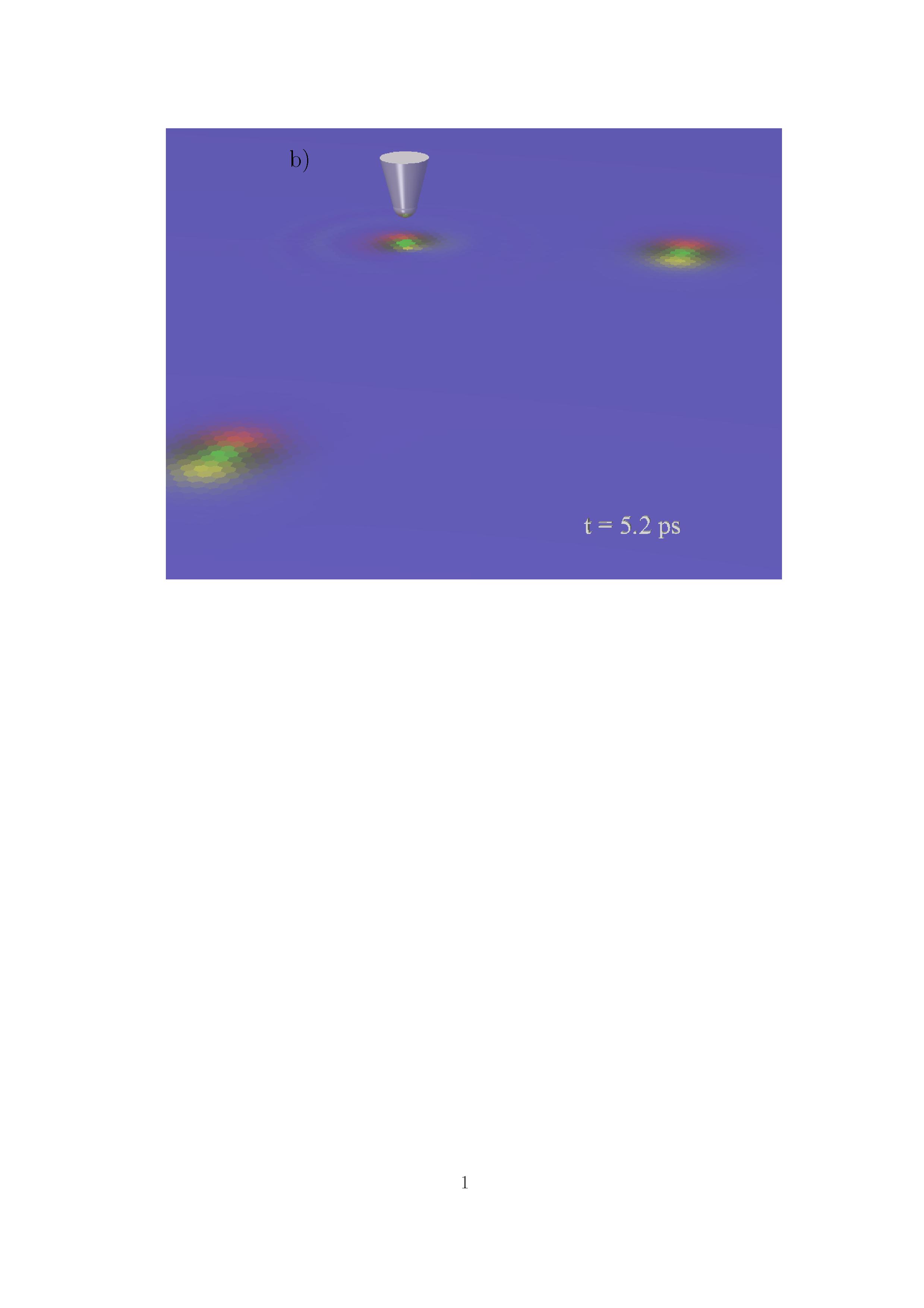
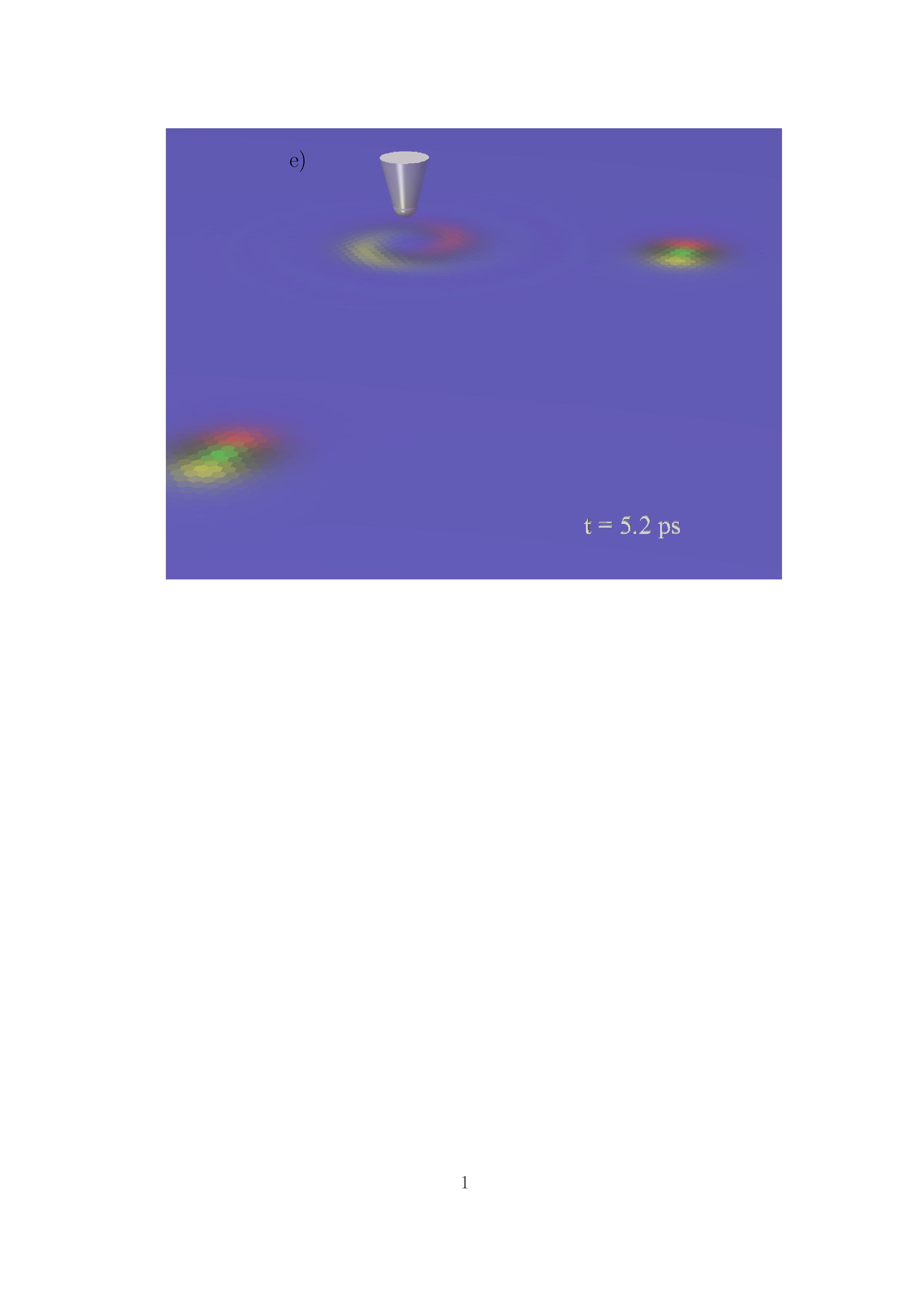

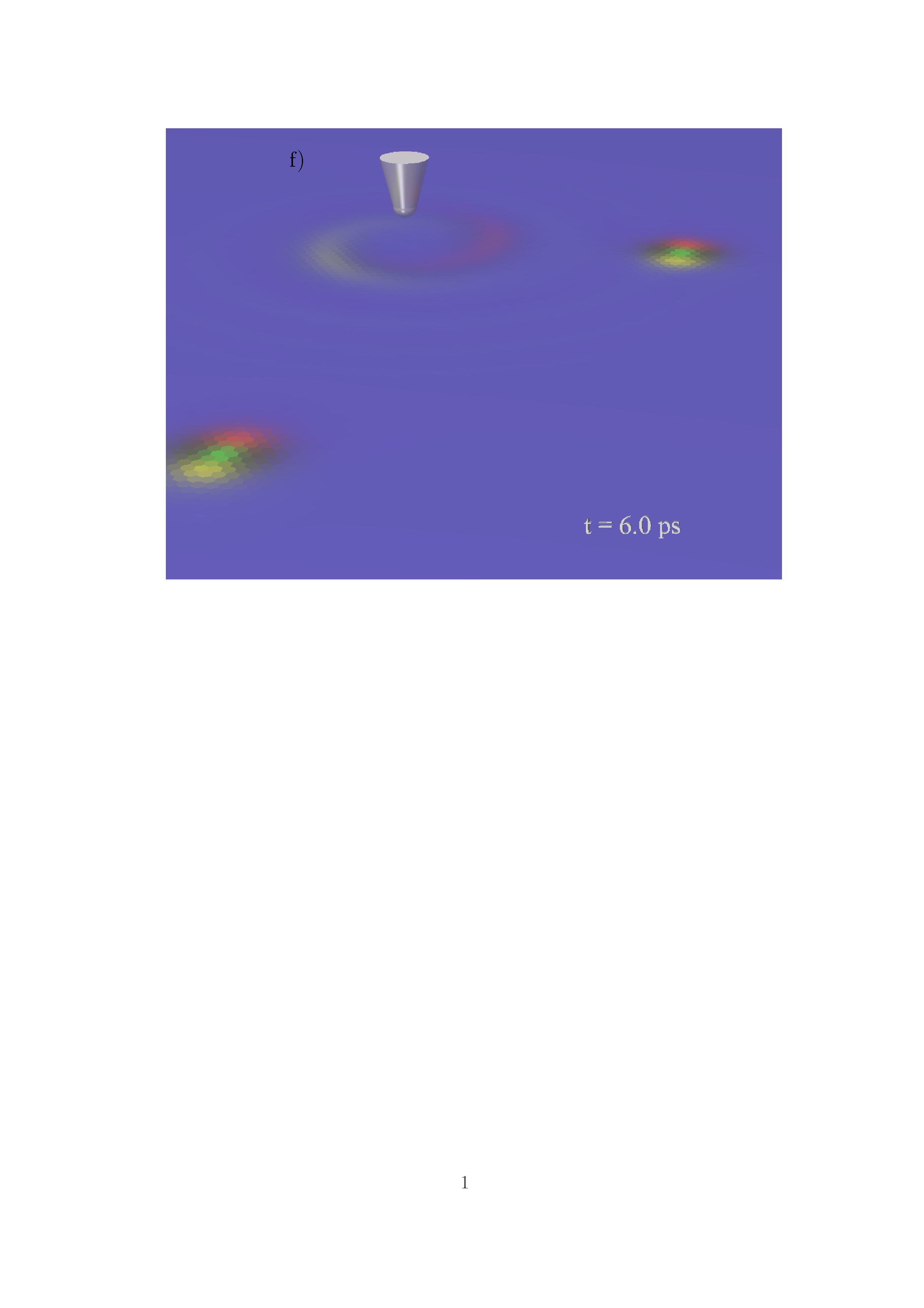
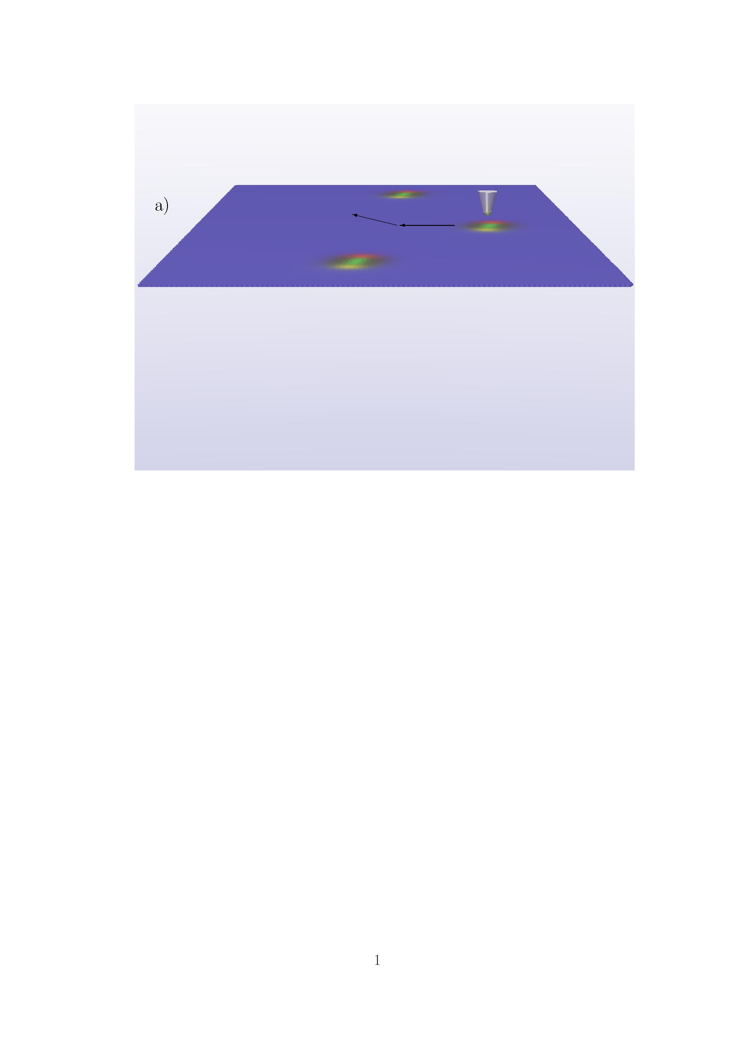

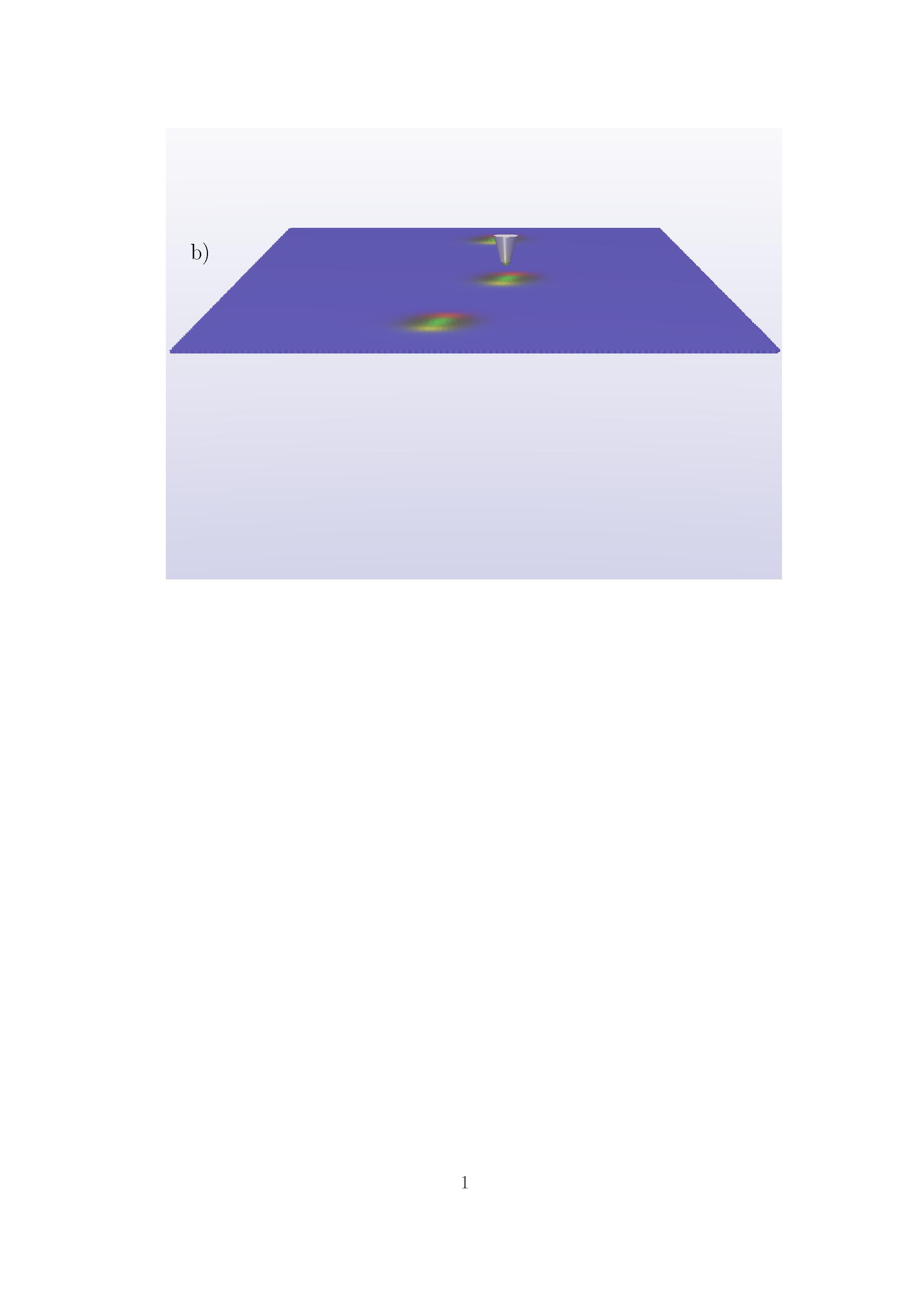
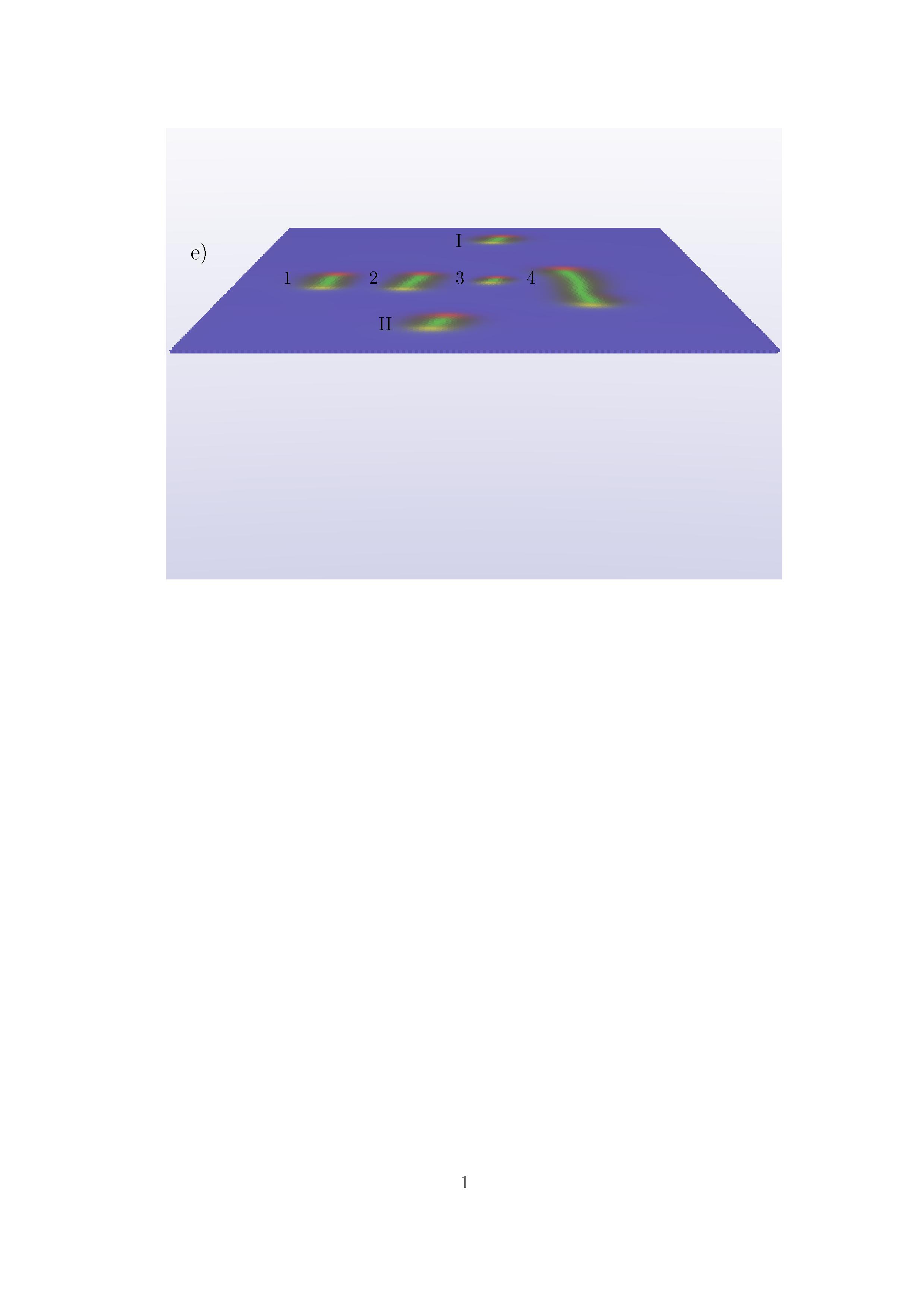
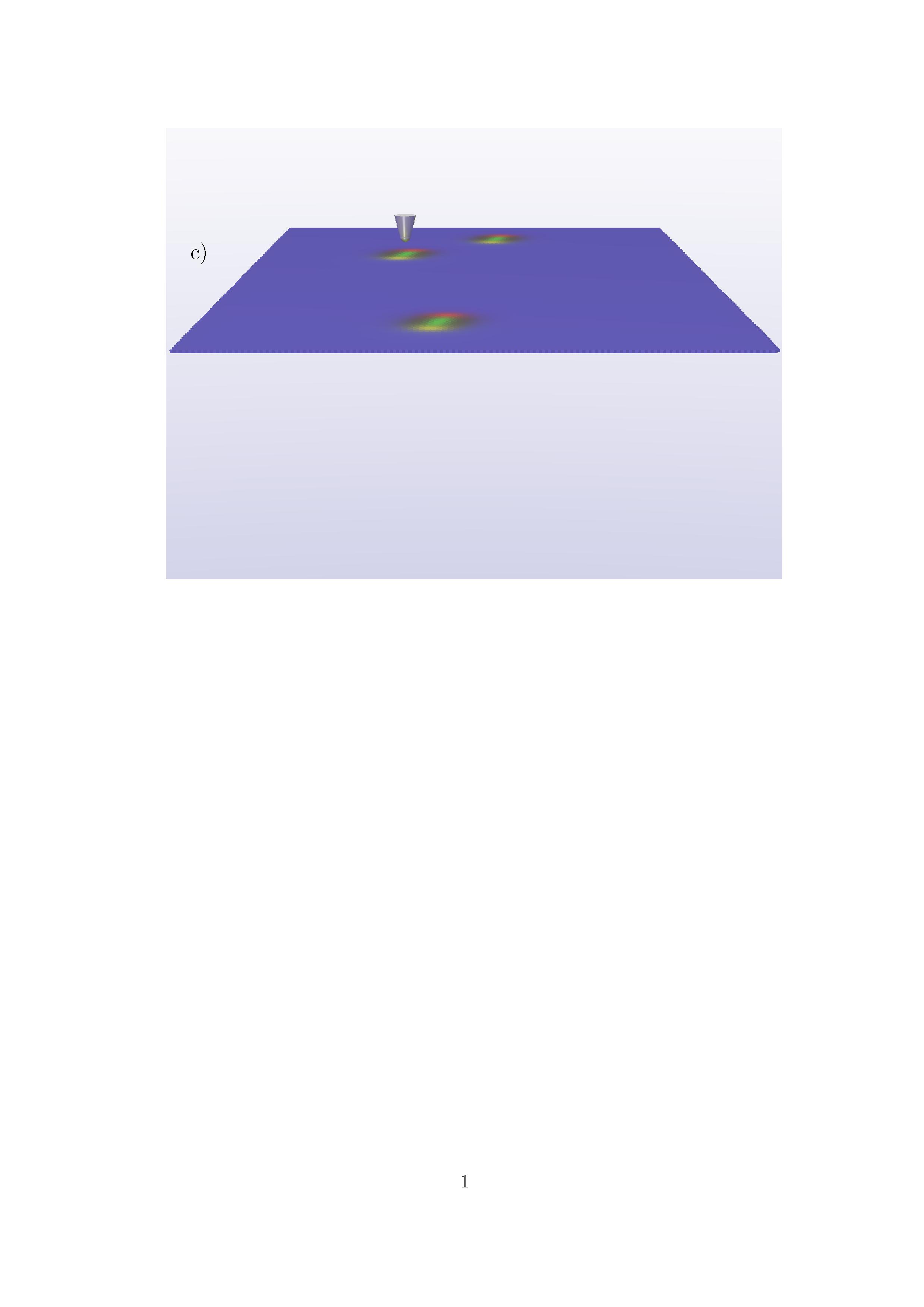

Fig. 2 provides a sequence of pictures showing the creation and annihilation of a magnetic Skyrmion with a spin-polarized tunnel current. The starting configuration with a ferromagnetic orientation of the magnetic moments underneath the STM tip is given in Fig. 2a). After a current pulse of ps with 1/s a Skyrmion is created. In total the creating process takes just a few pico seconds. Fig. 2b) and c) show two moments during the creation of the Skyrmion. The process starts with the reversal of the magnetic moments underneath the magnetic tip forced by the tunnel current. The tip polarization is assumed to be in -direction which is opposite to the orientation of the ferromagnetically aligned magnetic moments. After a short moment the Skyrmion configuration is created and the Skyrmion grows with the time. The size of the Skyrmion overpasses the size of the final configuration before it shrinks. During the shrinking the Skyrmion shows first a nonlinear excitations: fuzzy oscillation which becomes a breathing mode Liu et al. (2015); Kim and Garcia-Sanchez (2014) with frequency GHz. The final configuration is the Skyrmion shown in Fig. 2d). Another, current pulse with opposite tip polarization can be used to annihilate the Skyrmion. Fig. 2e) and f) show two snap shots of the destruction process. While during the Skyrmion creation the tunneling current has created a point singularity which becomes the center of the Skyrmion in the case of the annihilation process the tunnel current orients all spins underneath the tip parallel to the tip polarization. This means the tunnel current destroys the singularity and therefore the Skyrmion. It is a known fact that the central singularity is responsible for the stability of the Skyrmion (topological protection). Due to this singularity the Skyrmion has another topological charge than the Ferromagnet and the Skyrmion which stabilizes the Skyrmion.
Due to the locally appearance of the reversal process (just underneath the tip) and the fact that the system gains energy during the destruction of the Skyrmion (more precisely the singularity) the annihilation process appears like an explosion where a concentric shock wave starting underneath the tip and exciting the surrounding Skyrmions can be seen. The energy win just for the central spin can be easily calculated. In the case of a collinear structure and under the assumption of the Hamiltonian a reversed central spin with 6 nearest neighbors will set free an energy of .
Despite the creation and annihilation of Skyrmions the scanning tunneling microscope can be also used to move Skyrmions. The possibility to shift domain walls has been discussed in Stapelfeldt et al. (2011); Wieser et al. (2012). Fig. 3a) shows a sequence of pictures where the movement of a single Skyrmion with a moving scanning tunneling tip is demonstrated. The tip has a polarization in -direction which is opposite to the orientation of the ferromagnetic surrounding of the Skyrmion but parallel to the orientation in the center. In the former publications it has been shown that a tip polarization parallel to the magnetization in the center of the domain wall is the best choice. In the case of the Skyrmion a tip polarization parallel to the central magnetization is the best decision and has been used during the simulations. Furthermore, has been set to 1/s. At this point it has to be said that the velocity of the domain wall is equal to the velocity of the tip. This can be seen as an disadvantage because the STM tip velocity is very low. What happens if the tip moves to fast can be seen in Fig. 3b). Here, a larger current intensity ( 1/s) has been assumed. In this case the current creates a Meron which is not stable. The Meron collapses into several shorter Merons which become under rotational movements Skyrmions. The rotations of these Merons lead to interaction between them in such a way that they push each other. During the simulation a rotation of two Skyrmions around each other can be seen. The Roman and Arabic numbers in Fig. 3d)-f) give the positions of the original and created Skyrmions. This scene remembers the rotational motion of two identical masses around the center of mass and has been reported in the case of Skyrmions in multilayer systems Dai et al. (2014) as well as for pairs of vortices Völkel et al. (1991); Buchanan et al. (2005).
In the previous investigations within this Letter the Skyrmion has been manipulated with aid of a spin-polarized tunnel current. However, using spin polarized current means that it is needed to have a stable spin-polarized tip. Furthermore, a tip polarization is needed which is opposite to the external field. Due to these conditions it is more effective if the manipulation could be done with an unpolarized tip. Recently Hsu et al. Hsu et al. (2016) have shown that it is possible to create and annihilate Skyrmions by using electric field pulses. The performed simulations show that all the scenarios presented before: moving, creating and annihilating of Skyrmions can be done with an electric field. The electric field itself is local and affects locally the DMI Siratori and Kita (1980); Chen and Sigrist (2015):
is the original DMI without electric field, is the electric field vector, is the vector pointing from lattice site to lattice site , and is a constant. If, as in the experiment the electric field is given by a vector pointing in -direction (perpendicular to the film plane) will be parallel/antiparallel to the DMI vector and increases or decreases the effect of the DMI. This means especially if the electric field is oriented in such a way that it neglects the DMI the Skyrmion gets annihilated. Without DMI the ferromagnetic configuration is the ground state and the magnetic field which has stabilized the Skyrmion before destroys it now. The dynamics here is similar to the one described in Siemens et al. (2016). Two phases can be observed: first the reduction of the Skyrmion size and then the reversal of the center of the Skyrmion. During this reversal process the Skyrmion releases energy which can be seen in form of a concentric shock wave running through the system. During the first phase (reduction of the radius) the Skyrmion shows a twist of the magnetic moments which ends with the annihilation of the Skyrmion. The creation process of a Skyrmion is a little bit more complex. Here, the electric field strengthens the DMI. However, this is not enough to create the Skyrmion. To create the Skyrmion and the corresponding topology first the symmetry of the ferromagnetic order needs to be broken. In other words first a singularity which becomes the center of the Skyrmion has to be created. Here, temperature fluctuations and especially the Joule heating helps. Koshibae and Nagaosa have shown that a locally increased temperature can be used to create a Skyrmion Koshibae and Nagaosa (2014). Within the simulations a local increased temperature K has been used to locally break the ferromagnetic symmetry. Another ingredient which can help to create the Skyrmion is the fact that electric field not only changes the strength of the DMI, but also the strength of uniaxial anisotropies Zhou et al. (2014); Hibino et al. (2015). To move the Skyrmion an electric field with the same field direction as used for the creation of the skyrmion (in the case of Hsu et al. Hsu et al. (2016) pointing away from the film plane) can be used. Here, the electric field increases the DMI and therefore decreases the energy of the Skyrmion. The movement of the STM tip with adequate velocity let the Skyrmion follow. Thereby the dynamics is the same as using a spin polarized tunnel current.
In summary: computer simulations of a Skyrmion in a atomic spin system with triangular lattice have been performed. It has been shown that it is possible to use a scanning tunneling microscope to manipulate: create, annihilate and move a single Skyrmion, either by a spin polarized current or an electric field. The creation and annihilation of the Skyrmion reproduces the results of the experiments. However, the time average of a conventional STM is to low to see the dynamics during these events. The performed simulations deliver the missing information and give an explanation for the underlying physics. The aimed motion of the Skyrmion has not been demonstrated in experiments so far but the performed simulations show the possibility.
References
- Zhang et al. (2015a) X. Zhang et al., Sci. Rep. 5, 7643 (2015a).
- Zhou and Ezawa (2014) Y. Zhou and M. Ezawa, Nat. Commun. 5, 4652 (2014).
- Fert et al. (2013) A. Fert, V. Cros, and J. Sampaio, Nat. Nanotech. 8, 152 (2013).
- Zhang et al. (2015b) X. Zhang, M. Ezawa, and Y. Zhou, Sci. Rep. 5, 9400 (2015b).
- Zhang et al. (2015c) X. Zhang et al., Sci. Rep. 5, 11369 (2015c).
- O’Dell (1986) T. H. O’Dell, Rep. Prog. Phys. 49, 589 (1986).
- Parkin et al. (2008) S. S. P. Parkin, M. Hayashi, and L. Thomas, Science 320, 190 (2008).
- Wieser et al. (2006) R. Wieser, U. Nowak, and K. D. Usadel, Phys. Rev. B 74, 094410 (2006).
- Yamada et al. (2007) K. Yamada et al., Nat. Mater. 6, 269 (2007).
- Jiang et al. (2015) W. Jiang et al., Science 349, 283 (2015).
- Woo et al. (2016) S. Woo et al., Nat. Mater. 15, 501 (2016).
- Mühlbauer et al. (2009) S. Mühlbauer et al., Science 323, 915 (2009).
- Romming et al. (2013) N. Romming et al., Science 341, 636 (2013).
- Barker and Tretiakov (2016) J. Barker and O. A. Tretiakov, Phys. Rev. Lett. 116, 147203 (2016).
- Lin (2016) S.-Z. Lin, Phys. Rev. B 94, 020402(R) (2016).
- Hsu et al. (2016) P.-J. Hsu et al., arXiv 1601.02935v1 (2016).
- Hagemeister et al. (2015) J. Hagemeister et al., Nat. Comm. 6, 9455 (2015).
- Siemens et al. (2016) A. Siemens et al., New J. Phys. 18, 045021 (2016).
- Ezawa (2011) M. Ezawa, Phys. Rev. B 83, 100408(R) (2011).
- Liu et al. (2015) Y. Liu, H.Du, and A. Du, Phys. Rev. B 91, 094425 (2015).
- Kim and Garcia-Sanchez (2014) J. Kim and F. Garcia-Sanchez, Phys. Rev. B 90, 064410 (2014).
- Stapelfeldt et al. (2011) T. Stapelfeldt et al., Phys. Rev. Lett. 107, 027203 (2011).
- Wieser et al. (2012) R. Wieser et al., Europhys. Lett. 97, 17009 (2012).
- Dai et al. (2014) Y. Dai et al., Sci. Rep. 4, 6153 (2014).
- Völkel et al. (1991) A. R. Völkel et al., Phys. Rev. B 43, 5992 (1991).
- Buchanan et al. (2005) K. S. Buchanan et al., Nat. Phys. 1, 172 (2005).
- Siratori and Kita (1980) K. Siratori and E. Kita, J. Phys. Soc. Jpn. 48, 1443 (1980).
- Chen and Sigrist (2015) W. Chen and M. Sigrist, Phys. Rev. Lett. 114, 157203 (2015).
- Koshibae and Nagaosa (2014) W. Koshibae and N. Nagaosa, Nat. Commun. 5, 5148 (2014).
- Zhou et al. (2014) W. J. Zhou et al., Sci. Rep. 4, 4117 (2014).
- Hibino et al. (2015) Y. Hibino et al., Appl. Phys. Express 8, 113002 (2015).