On radiative acceleration in spine–sheath structured blazar jets
Abstract
It has been proposed that blazar jets are structured, with a fast spine surrounded by a slower sheath or layer. This structured jet model explains some properties of their emission and morphology. Because of their relative motion, the radiation produced by one component is seen amplified by the other, thus enhancing the inverse Compton emission of both. Radiation is emitted anisotropically in the comoving frames, and causes the emitting plasma to recoil. As seen in the observer frame, this corresponds to a deceleration of the fastest component (the spine) and an acceleration of the slower one (the layer). While the deceleration of the spine has already been investigated, here we study for the first time the acceleration of the sheath and find self–consistent velocity profile solutions for both the spine and the sheath while accounting for radiative cooling. We find that the sheath can be accelerated to the velocities required by the observations if its leptons remain energetic in the acceleration region, assumed to be of the order of 100 Schwarzschild radii, demanding continuous injection of energetic particles in that region.
keywords:
Galaxies: BL Lacertae objects: general — Radiation mechanisms: non-thermal — Relativistic processes —1 Introduction
Relativistic jets in low-power radio–loud active galactic nuclei (AGN) are thought to be structured, namely composed of a fast central part, that we call the spine, and a sheath or a layer surrounding it, moving at a slower speed. There are several arguments that support the structured jet hypothesis. It is very unlikely that the jet plasma moves with a large bulk Lorentz factor ( 10–15) inside the jet and with just outside it. The velocity of the plasma should decrease gradually across the edge of the jet because of shear viscosity and/or Kelvin–Helmoltz instabilities (e.g., Henri & Pelletier 1991; for a review see Ferrari 1998; see also Bodo et al. 2003). Structured jets could also result from the acceleration mechanism itself (e.g., McKinney 2006).
Observationally, the emission of high energy –ray radiation requires a large bulk Lorentz factor in blazars (i.e., sources whose jets are pointing at us), to avoid suppression by the e± process. Low-power, TeV emitting BL Lacs require the largest values of among all blazars (Tavecchio et al. 2001, Kino, Takahara & Kusunose 2002; Katarzynski, Sol & Kus 2003; Krawczynski, Coppi & Aharonian 2002; Konopelko et al. 2003; Tavecchio et al., 2010). However, the Large Area Telescope (LAT) onboard the Fermi satellite has detected (low-power) radio galaxies at GeV energies (Abdo et al. 2010; Grandi 2012). Their radiation cannot be the de–beamed emission coming from plasma moving with , since the de–beaming would be too strong, making the flux undetectable. The GeV radiation of radio galaxies must be produced by material moving with (Ghisellini, Tavecchio & Chiaberge 2005) which is high enough to avoid the absorption process but sufficiently small to avoid strong de–beaming of the flux.
Detailed VLBI radio maps of Mkn 501 revealed a limb brightening morphology, interpreted as evidence of a slower external flow surrounding a faster spine (Giroletti et al. 2004). Similar results have been obtained for Mkn 421 (Giroletti et al. 2006), 0502+675 and 1722+119 (Piner & Edwards 2014).
In addition to the above evidences for structured AGN jets, there is also mounting evidence for a decelerating spine in TeV BL Lacs, and therefore radial structure. Many TeV BL Lacs are not superluminal sources at the pc scale (Edwards & Piner 2002; Piner & Edwards 2004, 2014; Piner, Pant & Edwards 2010, 2008) even though they require the highest bulk Lorentz factors in the TeV emitting region (that is in most, but not all, cases located at sub–pc distances from the black hole).
Georganopoulos & Kazanas (2003) proposed a model in which the jet has a fast inner part and a slower part further out. In their model, the fast base of the jet sees the radiation produced by the slower zone relativistically boosted. Analogously, the slow part of the jet sees the radiation coming from the fast base of the jet relativistically boosted. The radiation energy density seen by both components is amplified with respect to the pure one–zone model.
Ghisellini, Tavecchio & Chiaberge (2005) proposed a “spine–layer” (or spine–sheath) jet structure with the two components having different velocities (the spine is faster). As before, each component receives increased amounts of seed photons. In this configuration the fast spine could be decelerated by the Compton rocket effect (O’Dell 1981), justifying the decelerating jet model of Georganopoulos & Kazanas (2003). The spine–layer model has been successfully applied to explain the high energy emission of radiogalaxies (M87: Tavecchio & Ghisellini 2008; NGC 1275: Tavecchio & Ghisellini, 2014; 3C 66B: Tavecchio & Ghisellini 2009) and slightly misaligned blazars (PKS 0521–36: D’Ammando et al. 2015). It has also been shown to help the production of high energy neutrinos in the relativistic jet of radio–sources (Tavecchio, Ghisellini & Guetta 2014).
In the original model and in the later application to specific sources, the velocity of the layer was a free parameter, and was assumed to be constant. On the other hand, the emitting plasma of the layer, being illuminated by the photons of the spine, emits anisotropically in its comoving frame and thus must recoil. The relative bulk Lorentz factor between the two structures is therefore bound to decrease, limiting the seed amplification effect leading to the extra inverse Compton emission.
In the initial jet zone (where there is no radiative interplay between the spine and the layer), the jet launching mechanism could itself be responsible for accelerating both the spine and the layer (e.g. McKinney 2006). An alternative option is that this launching mechanism is responsible only for the acceleration of the spine, while the layer gets accelerated radiatively. The aim of this paper is to study self-consistently the photon-mediated interaction between the two jet components that move with high relative velocity and thus find out which of the two options is preferred. In particular, we aim to explore and describe the dynamic coupling of the two radial components and to better understand this physical feedback process, as it could be important for relativistic jets in general, including Gamma Ray Bursts (e.g., Rossi et al. 2002; Lazzati & Begelman 2005).
This paper is organized as follows: in § 2 we discuss the setup of the model and the assumption made to make it mathematically tractable. In § 3 we present and discuss our results, and this is followed by our conclusions in § 4. We divide the study in five parts: i) we find the velocity profile of the layer assuming a constant spine velocity, and assuming a fixed energy distribution of the emitting electrons in the spine–layer system; ii) we study the layer motion assuming that the emitting electrons are injected at the start, and then radiatively cool; iii) we explore the layer’s motion for a case where the injected electrons maintain a fixed energy distribution inside a fixed volume (this fixed volume is discussed in greater detail in § 2.1) and cool radiatively once the plasma exits that volume; iv) we self–consistently calculate the motion of the spine and the layer, under their reciprocal radiative influence; and v) we study how the self–consistent motion of the spine–layer system is influenced by electron–positron pair loading.
2 Set up of the model
Our model consists of a cylindrical spine–layer structure as shown in Fig. 1.
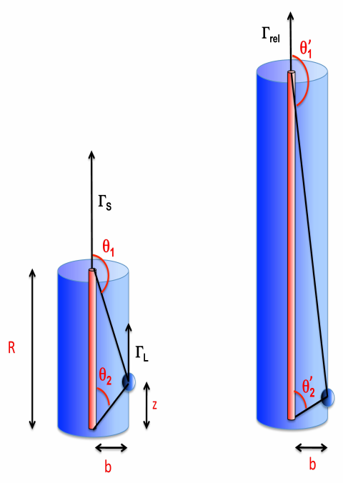
This structure is a system of concentric cylinders with the spine being the inner cylindrical structure and the layer surrounds it. We use this model to describe the dynamical evolution of the spine and the layer due to Compton scattering by photons produced by the layer and the spine respectively. The physical quantities of interest for investigating this problem are measured in three different reference frames. These three frames are:
-
1.
The observer frame : the quantities measured in this frame are identical to those measured by an observer on Earth, hence we will refer to this frame as the “observer frame”. Any quantity measured in this frame will be marked as unprimed.
-
2.
The layer frame : This is the frame instantaneously at rest with respect to the layer. It moves with respect to the observer frame at a variable Lorentz factor, denoted by . The quantities measured in this frame are marked with a single prime, e.g., is the spine luminosity as observed in the frame instantaneously co-moving with the layer.
-
3.
The spine frame : This frame is co–moving with the spine plasma with a Lorentz factor . The quantities measured in this frame are marked with a double prime, e.g., is the layer luminosity as measured in the spine frame.
2.1 Assumptions
We simplify the analysis of our spine–layer model by assuming that the spine is uni–dimensional and is in motion with an initial Lorentz factor (measured in the observer frame) along the jet–axis direction (referred to as –axis) as is depicted in the left panel of Fig. 1 by the inner cylinder. The layer is the outer cylinder surrounding the spine, has a radius of cm and, like the spine, travels along the jet axis with an initial Lorentz factor given by (subscript L denotes layer which we shall use synonymously with the sheath).
In our model we assume that the both the spine and the layer are ‘active’ only between two points which are fixed in the observer frame and separated by a distance of cm, implying the emitting volume to be fixed in that frame. Such an active region can be a result of a standing shock, where energy dissipation happens between fixed points. Both the spine and the sheath emit radiation isotropically in their respective reference frames, however any other frame would observe the emissions to be beamed. We thus introduce the relativistic Doppler factor (hereafter beaming factor) as:
| (1) |
which is the beaming factor of the radiation produced in the layer frame as seen in the observer frame. is the angle between the jet axis and the line of sight as measured in the observer frame.
| (2) |
is the beaming factor of the radiation produced in the spine frame as seen in the observer frame, and
| (3) |
is the relative beaming factor of the radiation produced in the spine frame and as seen in the layer frame (see also Georganopoulos & Kazanas 2003; Ghisellini et al. 2005).
The forces resulting from Compton scattering of the layer particles by the spine photons can drive/accelerate the sheath (in this work we consider scattering only within the Thomson regime). As the seed photons of Compton scattering are produced outside the layer, if the scattering particles are hot in , the scattered radiation is anisotropic also in the layer co–moving frame, making the layer recoil. For this reason, this interaction is often called Compton Rocket (Sikora et al., 1996; Ghisellini & Tavecchio, 2010; Vuillaume, Henri & Petrucci, 2015) and for hotter particles this driving force increases proportionally to their average internal energy .
We assume that the layer particle is free to move in the direction parallel to the jet axis. For simplicity, we assume that the distance between the layer and the jet axis, , is fixed, despite the presence of a radial radiative force, and thus also along the normal to the jet axis. This can be achieved through the presence of a magnetic field. To analyze the motion of the sheath we consider an infinitesimal part of the sheath at a position which we treat as an “effective particle”. The constituent particles inside the layer are representative of the sheath particles and the sheath can be thought of as composed of a collection of these effective particles (see also §2.3).
The right panel of Fig. 1 depicts the structure as viewed in the frame of the sheath. The sheath finds the spine moving at a Lorentz factor and due to the aberration of light observes the vertical dimension of the active region to be larger than . We assume that the observer is located at a viewing angle of .
2.2 Particle distributions and cooling
We assume that the particle distributions in the spine and the sheath to be a broken power law, with slope below and (where ) above the break :
| (4) |
where is the maximum Lorentz factor of the distribution that depends on the cooling rate (see §2.2). For simplicity we omit hereafter the prime and the double prime for and . We can use the distribution to calculate the averages and as:
| (5) |
In our work we fix , and . A possible realisation of this case corresponds to continuous injection of electrons distributed as above , and below. If radiative cooling is fast (i.e., even particles with low Lorentz factors cool in a timescale shorter than the light crossing time), the stationary distribution will have a slope above and below. For (i.e., ) Eq. 5 gives:
| (6) |

If the injection of particles is not continuous, the high energy particles are not replenished any longer, and the distribution cuts–off at the cooling energy , which decreases with time. The cooling of the plasma impacts the particle energy distribution which in turn affects the force that these particles experience (see Eq. 9). Therefore we have to account for radiative cooling of the sheath/spine plasma due to irradiation by the spine/sheath photons. The cooling rate is (e.g. Rybicki & Lightman 1979):
| (7) |
where is the integrated radiation energy density in the layer frame, and are respectively the Lorentz factor and speed of the particle possessing the maximum internal energy (hence the subscript max) in a hot plasma. At each timestep we calculate the cooling Lorentz factor of the leptons using Eq. 7:
| (8) | |||||
We assume that the particle distribution vanishes for : the cooling Lorentz factor becomes the new maximum Lorentz factor of the distribution, i.e., . Since is time dependent, the averages and (see eqs. 2.2) also become time dependent. Graphically, the evolution of the averages as a function of the ratio (in other words, with time due to cooling) is depicted in the Fig. 2 for several power-law indices.
2.3 The equation of motion
In order to study the trajectory of the sheath or the layer, we require the equation of motion given as
| (9) |
where d and d are calculated in the same frame (any frame), but is calculated in the frame comoving with the particle (see e.g. Weinberg, 1972). Since we assume that the layer and the spine are optically thin, we can calculate the motion of a single particle due to Compton scattering. We define as the ratio of number of leptons to protons and indicates the presence of pairs in the plasma. This enables us to study the motion of an “effective particle” of inertial mass , where the electron mass is multiplied by to account for the average internal energy of the leptons. Equation 9 can be written as:
| (10) |
We begin by considering the motion of the layer due to the interaction with the
radiation produced by the spine (moving with a constant bulk Lorentz factor ).
In this case, the driving force can be computed by considering the flux received by a particle in the layer located at a given .
This flux will be produced at different heights of the spine, seen under
a different angle and with a different beaming.
Therefore we will have to integrate over the entire length of the spine while accounting for the different degrees of relativistic effects.
From the detailed calculations as shown in the appendix, we write the equation of motion
(Eq. 10) as:
| (11) |
where is a factor of the order of unity that depends on the geometry of the system (in this case we used ), is the spine comoving linear luminosity density which is connected to the spine isotropic luminosity .
2.3.1 The drag Lorentz factor
This section introduces the physical meaning of drag Lorentz factor which we will frequently use to understand our results. is the value of for which the component of the force as measured in the comoving layer frame vanishes. The net force acting on the effective layer particle at a certain position is computed by accounting for photons that hit the effective particle both from above and below its position. As seen in the observer frame , photons that hit the sheath “effective particle” with an incident angle less than with respect to the sheath’s direction of motion appear to arrive from above the effective particle’s position in the sheath comoving frame. These photons decelerate the particle by imparting negative momentum (negative force). On the other hand, photons that are incident with an angle greater than will accelerate the particle, generating a positive force. The value of the layer Lorentz factor for which these positive and negative forces are equal is called the drag Lorentz factor. Its value as a function of can be obtained by imposing the condition that , and this simplifies Eq. 11 to:
| (12) |
Since the sign of the total force depends only on the sign of the integral in Eq. 11 or Eq. 12, we will have:
2.4 Feedback
The previous subsections describe the dynamical evolution of the sheath plasma interacting
via Compton scattering with the spine photons.
However, we ignored the effect of the sheath photons on the spine to simplify the analysis.
In this section, we relax that assumption by accounting for the
interaction of the layer photons with the spine and how this interaction modifies
the spine Lorentz factor .
As a result, we can explore how the feedback between the spine–layer structure self regulates its very own dynamical evolution.
To study the
spine–layer feedback, we need to modify some equations of the previous section according to the following considerations:
-
•
As the bulk Lorentz factors for both the spine and the layer can be modified, we must compute two profiles and for the spine and the layer respectively.
-
•
The linear luminosity density profiles of the spine and the layer ( and ) can vary with position, but we assume that the comoving luminosity density profiles are proportional to the average square of the particle energies constituting the emitting plasma, i.e., and . Thus, if the internal energy content of the plasma changes by radiative cooling, the comoving luminosity profile will no longer be independent of the position.
-
•
We take advantage of the symmetry of the problem and suppose that the effect of the spine on the layer and the inverse effect, i.e., of the layer on the spine can be expressed by the same relations by simply switching the subscripts.
These considerations lead to the following system of differential equations describing the evolution of two “effective particles” that represent the spine and the layer (having masses and for the spine and the layer respectively):
| (13) |
All the important steps leading to the above equations are fully described in the Appendix, along with the limits of integrations , (which can be obtained using the Eqs. 27 and 28 respectively). We can compute the Lorentz factor profiles and by numerically solving this system. The reader should note that the acceleration of the layer (spine) depends linearly on the product of the isotropic luminosity of the spine (layer) and the average of the square of the leptonic Lorentz factor of the layer (spine). We call this product :
| (14) |
Hence we treat this product as a single parameter.
3 Results and Discussion
In this section we present and discuss the results of the numerical integration of the equations of motion considering different conditions:
3.1 Radiative acceleration of the layer: No cooling scenario
In this section we start with the simplest and somewhat unrealistic scenario where:
-
i)
the spine moves with a constant bulk Lorentz factor (not considering its deceleration due to layer photons);
-
ii)
the sheath particle distribution does not change with time (i.e., the particles do not cool by radiative emission, or the cooling is exactly compensated by injection of new particles).
By switching ’off’ the cooling we have made this scenario somewhat unrealistic, but this simplifies the problem at hand and in turn allows us to gain greater insight and develop intuition about the radiative acceleration phenomena. This will help to improve our understanding of more complex scenarios discussed later in the paper. We solve the equation of motion of the layer under different conditions (however we only vary a single parameter in each case to develop intuition) and we show the spatial profiles of and of the force perceived by the layer projected over the –axis .
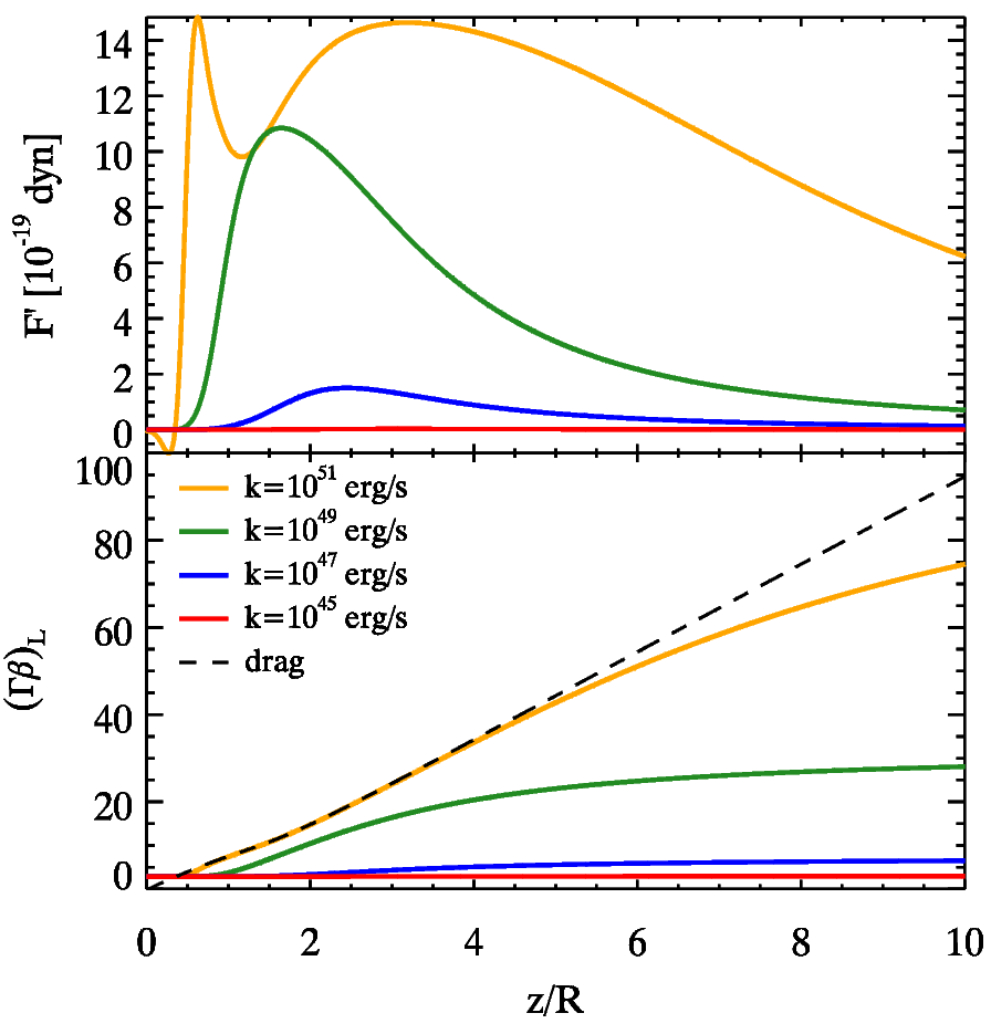

Varying —
Fig. 3 shows the effects of varying
for a constant spine Lorentz factor and an initial bulk Lorentz
factor of the layer .
At the base of the structure, i.e., for small values of , the forces are negative for all the curves irrespective of the value (the yellow curve has the greatest magnitude and hence is clearly visible below the zero force mark, whereas the other curves experience comparatively much smaller forces which are difficult to resolve on the scale of Figure 3).
This is due to the fact that at the start () the layer particle sees a greater fraction of the radiation directed downward due to the entire spine–sheath structure located ahead. This decelerates the sheath thereby decreasing the as can be seen in the second panel, where the Lorentz factor profiles
are compared with the drag Lorentz factor.
We start the simulations with a
value of which exceeds the drag Lorentz factor at that position.
As a result negative forces arise from the drag effects to reduce Lorentz factor at
(or below) the drag level (refer to § 2.3.1).
We note that the force increases with the increasing values of
as seen from the
force curves in the top panel of Fig. 3.
For low spine luminosities or if the sheath plasma has small
internal energy (the case of a cold plasma with low value of
) we find that the layer accelerates negligibly.
Instead, significant acceleration is observed by increasing the spine luminosity
or the mean squared energy of the particle in the layer.
In such cases, the bulk Lorentz factor profile
manifests an initial decrease due to the initial negative force and then a subsequent increase.
This increase, at the beginning, follows the drag Lorentz factor profile but it flattens afterwards
depending upon :
the greater the value of , the greater the final value of
and the longer the time for which the bulk Lorentz factor profile follows
the profile.
The curves with the highest ( erg s-1) display a peculiar force profile characterized by a double peak shape. This behavior is due to a confluence of two effects. Increasing the force increases and if it approaches and attempts to surpass the drag limit, the force rapidly decreases (refer to § 2.3.1). Thus, the drag effect is responsible for producing the rapid drop and consequently, the first peak in the force profile. The second effect is due to the fact that when the layer effective particle surpasses the length–scale of the structure , it receives most of the radiation produced by the entire spine length (pushing the effective particle along the positive direction), which lies behind the particle. This produces the second maximum of the force profile. Note that the double peak is absent when the layer bulk Lorentz factor is nowhere near the drag limit.

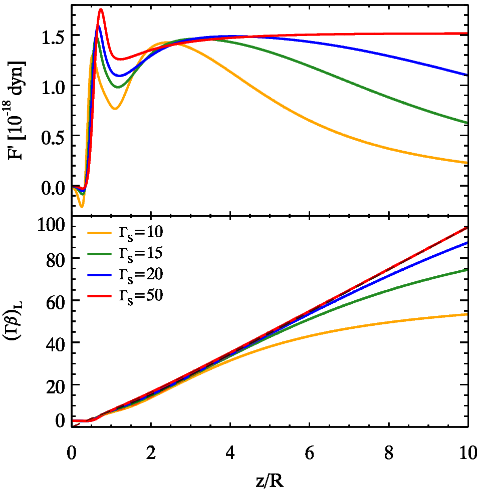

Varying — Fig. 4 shows the effects on radiative acceleration of the layer due to variation in the initial layer bulk Lorentz factor . The other quantities that remain fixed are the average internal energy content of the sheath leptons () and the isotropic spine luminosity erg s-1. In all cases, the force profile is characterized by the same features as observed in Fig. 3: initial negative force and double peak shape. However due to the different values of , the force magnitudes for the various curves are initially different, with the curves traveling at larger experiencing initially a larger force which decelerates them below the drag limit. We also note an interesting merging feature of both the and the force curves. With identical forces and Lorentz factor , we expect and observe the trajectories of the curves to remain merged. This feature suggests that, in case of hot plasma and for , the dynamical evolution of the layer does not depend on its initial Lorentz factor .
Fig. 5 depicts the radiative evolution of a cold plasma () for an isotropic spine luminosity ( erg s-1) and a constant spine Lorentz factor of . The value of for Figs. 4 and 5 differs by which is the average of the square of the leptonic Lorentz factor for the hotter plasma. We continue to vary as our parameter and by comparing the two figures (Fig. 5 and Fig. 4) we note that the forces experienced by the colder leptons are smaller by two orders of magnitude. This strong reduction in the force results in negligible acceleration of the layer effective particle which maintains its initial Lorentz factor except for the case , where there is a weak increase of the bulk Lorentz factor to . We also note that as the forces involved are smaller than the previously considered cases, the drag force is not strong enough to create multiple force peaks. Thus the force profiles are characterized by single peaks which occur when the radiation from the entire spine irradiates the sheath particle.
Varying — In the final case for this subsection, we explore the effects of varying on the force and curves for . If the sheath plasma is hot, we observe double peaked curves as shown in the top panel of Fig. 6. We also note that a faster spine produces a greater force on the sheath, resulting in a faster sheath. Fig. 7 shows the same physical quantities but for a cold sheath and we note that the forces involved are reduced by an order of magnitude. This does not result in a significant change of the layer Lorentz factors except for the case when , where a comparatively larger force leads to an accelerating sheath.

3.2 Radiative acceleration of the layer: cooling scenario
3.2.1 Single injection
In this subsection we explore a case where the particles of both the spine and the layer are energized only once before entering the active region and the particles in the layer can cool via radiative cooling. This implies that the layer leptonic energy distribution varies with time. For simplicity, we will assume here that the spine bulk Lorentz factor is constant, leaving the study of the possible change of (caused by the interaction with the layer photons) to § 3.3.
We start by solving the equation of motion for the layer and we show the spatial profiles for , the evolution of the average internal energy of the layer and the profile of the force as perceived by the layer projected over the -axis .
Varying — We begin by varying the intrinsic spine luminosity , assuming that the population of the sheath is initially hot (). The top panel of Fig. 8 depicts the force curves for different values of the spine luminosity. For small values of , the force profiles are similar to the profiles in Fig. 3. All the curves show an initial negative force with magnitudes proportional to the spine luminosity (refer to § 3.1). The middle panel shows the variation of and we note the difference in the cooling rates for the various curves, which arises because sheaths with more luminous spines cool faster. Note that the various curves in the second panel eventually merge due to continuous cooling. The third panel shows the variation of . For , all the layer curves show no acceleration. On the contrary, from the force curves one expects the layer to be decelerated due to the initial negative forces but these decelerations are small and hence difficult to resolve (and thus, see) in Fig. 8. However, the reader can observe the resolved deceleration for the blue curve in Fig. 8 through the red curve in the bottom panel of Fig. 9 because the product erg/s is identical for these curves. When the effective sheath particle overtakes the scale–length , the spine which lies behind it irradiates the particle from the rear. However, at these large values of the sheath plasma is cold and only extremely large spine luminosities (e.g. erg s-1) are capable of significantly accelerating the layer particle and hence the layer, as shown in Fig. 8.

Varying — We explore how the sheath evolves for different initial (in short, ) values under the influence of radiative cooling with an initial sheath Lorentz factor and a constant spine luminosity erg s-1. Fig. 9 confirms that the force profile is characterized by negative values during the initial stages, with the hottest sheaths experiencing the greatest force magnitudes. The middle panel depicts the variation in due to radiative cooling. The curves show an initial flat evolution and then a decreasing trend in such a manner that all the curves merge, irrespective of their values. This behavior can be understood from Fig. 2 or from particle energy distribution of the layer (see Eq. 4): if the cooling energy is greater than the spectral break energy (i.e., ), then which implies that is almost constant (this corresponds to the initially flat evolutionary phase seen in the middle panel of Fig. 9). However, when crosses , starts to decrease from its initial value and becomes comparable to . Note that even though the force curves have merged (simultaneously with the merging of curves), the curves remain segregated due to the different initial decelerations resulting from the different initial behavior of . This leads to the interesting result – the bulk Lorentz factor at saturation is maximum for an intermediate value of the initial (), instead of the curve with the initially hottest leptons (), albeit by a small amount (see Fig. 10).
As a whole, we conclude from this section that the radiative cooling process causes the layer to lose internal energy rapidly and so it quenches the process of radiative acceleration. Except for cases with very high spine luminosity, we can affirm that the final bulk Lorentz factor of the layer does not change significantly from its initial value (see Fig. 10). This result is similar to those obtained by studying the radiative acceleration of a cold plasma in the no cooling scenario (cfr. §3.1).
3.2.2 Continuous injection
This scenario explores the situation where we have continuous energy injection inside the
sheath region via, e.g., a standing shock, namely when the cooling is balanced by injection of
fresh energetic particles that energize the plasma and the electron energy distribution is assumed to stay constant between and cm.
There is no energy injection outside the active region.
We assume that the injection rate within the active region is
such that its effect is equivalent to making cooling ineffective.
We still neglect here the radiative effects on the spine due to the layer and hence the bulk
Lorentz factor of the spine is assumed to be constant.
Differently from most of the other cases presented in this work, for this case we assume that the initial bulk Lorentz factor of the layer is close to unity. In fact we intent to explore if the layer can be accelerated radiatively and, achieve a bulk Lorentz factor as required by observations.

Fig. 11 depicts the evolution of the force, and curves. The continuous shocking re-energizes the particles within the standing shock region, and it is responsible for large forces proportional to the plasma’s internal energy content. Because there is continuous energy injection for cm, we expect the physical quantities in this region to evolve in a fashion similar to the same quantities in § 3.1. Indeed, the evolution of the force curves in the standing shock region as depicted in Fig. 11 is very similar to Fig. 3 (the yellow curves are almost identical for ). The drop in the force is due to the bulk Lorentz factor of the layer approaching as explained earlier in § 3.1. All the three curves experience positive forces, leading to an accelerated layer as demonstrated by the plot in the bottom panel of Fig. 11. The cooling becomes effective for cm (), resulting in a rapid decrease in the values of for the various curves (middle panel of Fig. 11). A decrease in correspondingly produces a rapid decrease in the force values also (top panel of Fig. 11). The role of radiative cooling in quenching the radiative force has been explored in detail in § 3.2.1. As the force values for cm are quite small, we note that the layer Lorentz factors saturate close to the values attained at cm.
Fig. 11 shows that if the layer is kept hot by a mechanism replenishing its energy losses, it can indeed be accelerated to “interesting” Lorentz factors (i.e. ). Of course, the hotter the layer, the stronger the Compton rocket effect and the larger the final Lorentz factor. We will see in the next subsection if this remains true when considering the feedback on the spine.
3.3 Spine–layer feedback

In §2.4, we described the feedback mechanism produced by relative interaction between the photons emitted by the layer and the spine particles and vice–versa, i.e., between spine photons and layer particles. In this section we aim to study the spine–layer feedback mechanism and how the mechanism modifies the Lorentz factor profiles for both the spine and the layer. First we will compute both the spine and the layer bulk Lorentz factor profiles [ and ] in a self–consistent manner. Second, we will study two cases with and without the presence of radiative cooling: in the first case the particle energy distribution is fixed for both the spine and the layer, which is equivalent to the no cooling scenario (however here feedback is active). In the other case, both the spine and layer particles cool radiatively (with feedback).
The spatial profiles of the rest frame forces and of the bulk Lorentz factors for spine and layer have been computed by numerically solving Eqs. 13. The results for the two cases (with cooling and without cooling), mentioned earlier are shown in Fig. 12 and are be summarized below:
-
1.
As expected, in all the explored cases the spine is decelerated by the Compton interaction with the layer photons. The force experienced by the spine is always negative (the only exception is the case with , where in the last stages the spine force turns positive);
-
2.
consistent with the results of previous sections, the layer is initially decelerated and later accelerated in all cases;
-
3.
the acceleration is stronger for greater values of and is negligible for cold plasmas;
-
4.
the cooling case reproduces the results of a cold spine and a cold layer, i.e., no significant change of bulk Lorentz factor;
-
5.
for high values of the effect of deceleration of the spine and acceleration of the layer is so strong that the sheath can eventually travel faster than the spine. This occurs because the cooling has been switched off. We believe that this is rather unrealistic: to maintain such an energetic particle distribution a huge amount of energy must be supplied to the plasma.
3.3.1 Continuous injection with feedback

In this scenario we study the kinematic evolution of the plasma due to continuous injection (see §3.2.2) while taking into account the effects of spine–layer feedback. The initial internal energy content of the spine and the layer plasmas ( and respectively) is maintained by continuous injection of particles within the region thereby rendering radiative cooling ineffective. However, in the absence of particle injection, i.e., for radiative cooling becomes important and impacts the evolution of the plasma by altering its internal energy content (see §
2.2). This scenario differs from § 3.2.2 because here we account for the radiative interplay between the spine and the layer and, as a result, the bulk Lorentz factor and the average internal energy content of the spine are no longer constants.
In order to study if the layer can accelerate from almost ‘at rest’ situation and achieve bulk motions required for explaining observations, we begin with the layer moving at a small initial bulk Lorentz factor . The three panels, from top to bottom in Fig. 13 show how the forces, , and, the velocity profile for the spine and the layer evolve as a function of the normalized position . We summarize the results of Fig. 13 below:
-
1.
For the cases with different initial values, the spine predominantly experiences a negative force with a magnitude proportional to the spine’s internal energy content . The forces are quite small for and as a result negligible deceleration occurs in this case. The forces are significantly larger for cases with which result in the decelerating spine traveling slower than the layer. With the layer now moving faster than the spine, this ‘role reversal’ causes the spine to experience a positive and accelerating force. However, the magnitude of this force is small due to the reduction in the relative bulk Lorentz factor between the spine and the layer;
-
2.
the layer is first decelerated and then accelerated (due to the system’s geometry as explained in detail in § 3.1) as the top panel of Fig. 13 shows. However, for cases where the top panel depicts formation of a peak, followed by a decline in the layer force curves within the region . The peak’s location coincides with the location where the decelerating spine slows down to speeds comparable to those of the layer (see bottom panel) - leading to reduced relative motion which suppresses Compton rocket acceleration. As a result, the force experienced by the layer peaks and declines;
-
3.
the net acceleration of the layer does not generally correlate with the average internal energy content of the layer. This is evident from the hotter plasma (yellow curve - ) saturating at a lower speed than a cooler plasma (the red curve - ) as depicted in the bottom panel of Fig. 13. This phenomenon can again be linked with a hotter spine being more quickly decelerated than a comparatively cooler spine. For sufficiently hot plasmas, the decelerating/slowing spine can end up traveling at comparable or slower speeds than the layer which leads to lesser relative motion and, thereby, suppression of the Compton rocket mechanism;
-
4.
in the case (blue curve) the layer accelerates until , after which particle injection ceases, and radiative cooling rapidly decreases the layer’s internal energy content. As a result the gradually increasing radiative force vanishes and the acceleration process is quenched. Rapid radiative cooling also occurs for plasmas with (as shown by the red and yellow curves), and cools these plasmas faster than the case (blue curve) as shown in the middle panel of Fig. 13. Again, this leads to the sudden drop in the force curves and quenches any further acceleration. The velocity saturation and force quenching phenomena observed here are identical to those observed in § 3.2.2.
As shown in the bottom panel of Fig. 13, by replenishing the energy lost radiatively by injecting particles continuously the layer can attain and maintain “interesting” Lorentz factors (). Comparison between the results obtained here with those of § 3.2.2 shows that radiative feedback in hotter plasmas (both the spine and the layer are hot) reduces the relative bulk motion between the two components of the jet (i.e., the spine and the layer). This reduction in reduces the amount of boosted radiation thereby suppressing the Compton rocket effect. As a result, the layer does not accelerate and attain Lorentz factors beyond . Thus in this particular scenario, acceleration/deceleration due to radiative feedback is responsible for regulating the bulk Lorentz factors of both the spine and the layer.
3.4 Spine–layer feedback in e+e- pair loaded plasmas
In this subsection we explore the impact of electron–positron pair loading on the radiative acceleration of the spine and the layer. While accounting for radiative feedback between the spine and the layer we explore the effects that different amounts of pair concentrations can have on the spine–layer system. The main effect of pairs will be to make the plasma “lighter”, in the sense that the radiative force will act on an increased number of leptons, while the inertia is still dominated by the same number of protons (except for the pair–dominated cases). Therefore the acceleration or the deceleration will be stronger. The amount of pairs in the plasma can be characterized by the lepton to proton ratio (as defined in §2.3) as follows:
-
•
Pair–free (PF) plasma (): there is one proton for every electron and no pairs are present.
-
•
Pair enriched (PE) plasma (): this plasma is characterized by the presence of several electron–positron pairs. The value is about the maximum allowed from considerations about the total power of relativistic jets (Ghisellini & Tavecchio 2010).
-
•
Pair dominated (PD) plasma (): in this case leptons dominate the kinematics of the plasma. We show this case for illustration, even if it may not be realistic for AGN jets.
We will first study the case without feedback and with the spine moving with a constant bulk Lorenz factor . Then we will study the feedback case, assuming that both the layer and the spine have the same number of pairs. Within the case without feedback, we will study the extreme cases of a cold plasma (, Fig. 14) and a hot plasma (, Fig. 15). Finally, we study the feedback case (Fig. 16). The results of these cases are summarized as follows:
-
1.
Cold plasma – No feedback — Fig. 14 depicts the force experienced by the layer due to radiation from the spine in the upper panel. The lower panel depicts the radiative acceleration of the layer by plotting as a function of position . We note that the force magnitudes are extremely small dyn in comparison with forces observed in the earlier sections. The pair–free plasma case is identical to in § 3.3. Even though the forces are small, the increased pair content decreases the mass of the effective particles. Thus the greater the amount of pairs, the greater the acceleration, as shown by the bottom panel in Fig. 14.
-
2.
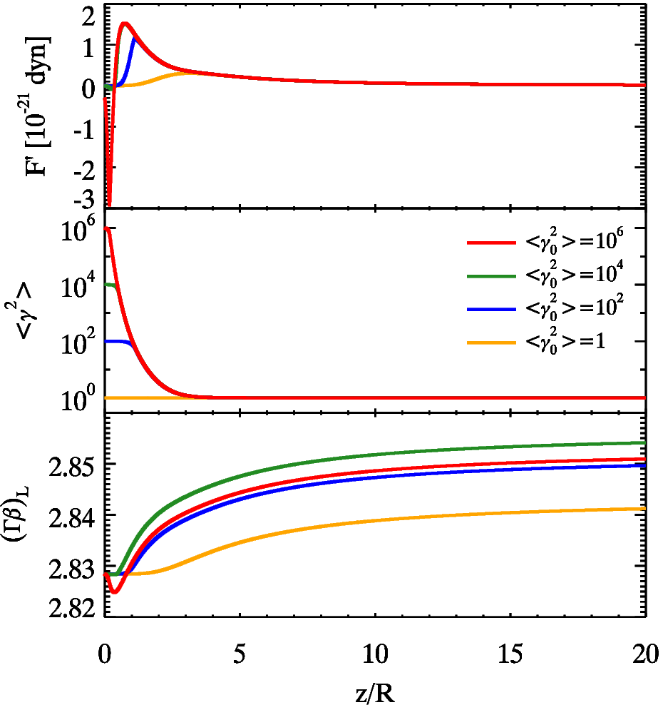
Hot cooling plasma – No feedback — We consider a hot plasma with with cooling enabled. Fig. 15 shows the force experienced by the layer (top panel), the variation of (middle panel) and the evolution of (bottom panel) as a function of . As expected, hotter plasmas experience a stronger and negative initial force which tends to decelerate them. The decelerations experienced depend upon the pair content, thereby the pair dominated plasma is decelerated more than the others. This slowing down of the plasma leads to a decrease of the (negative) force (due to the decrease of the received radiation energy density). This impacts the cooling rate as well as the force profile for the pair–dominated plasma. The lower cooling rate along with geometrical effect (entire spine irradiating the layer particle) is responsible for the burst in acceleration at large values of .
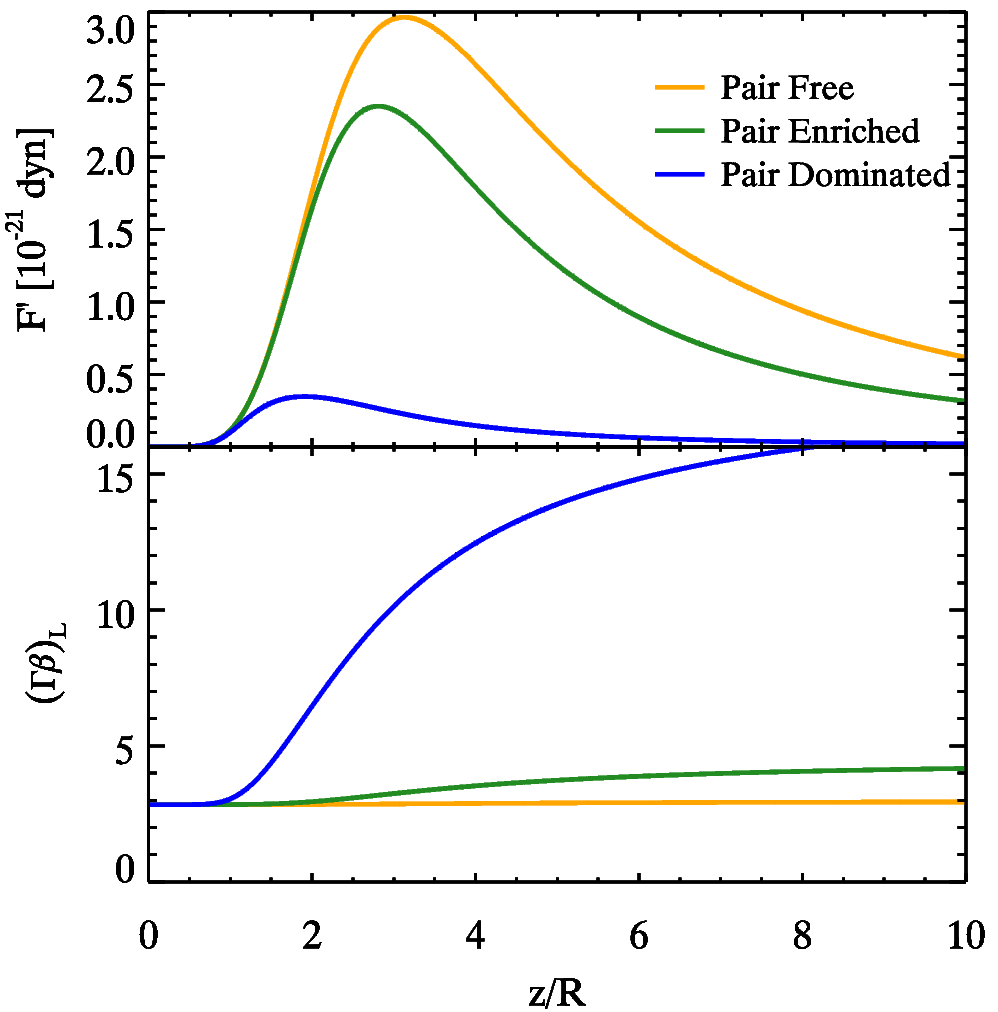
Figure 14: Radiative acceleration of a cold, pair–loaded layer plasma by varying lepton to proton ratio ; we analyze three cases with : no pairs in layer (); a plasma with and the extreme case of a pair dominated plasma. Parameters used: , and . Top panel: radiative force as measured in the layer frame. Bottom panel: profile of for the layer. 
Figure 15: Radiative acceleration plot for a hot layer plasma having different lepton to proton ratios ; we analyze three distinct cases with an initial : no pairs in layer and spine plasma (); a pair–enriched plasma, and the extreme case of a pair dominated plasma. Parameters used: , and . Top panel: radiative force measured in layer frame as a function of . Middle panel: the evolution of internal energy of the sheath denoted by . Bottom panel: profile of for the layer as a function of . 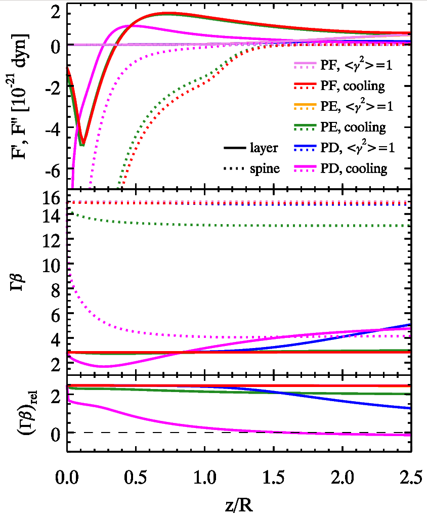
Figure 16: Radiative acceleration of the spine–layer pair loaded plasma with feedback; we compare and analyze three cases with different lepton to proton ratios: no pairs in the layer and spine plasmas (i.e. there is one lepton for each proton - PF); a plasma with leptons for each proton (PE) and as the final case, a plasma dominated by pairs (PD). Parameters used: , and . Top panel: Radiative force measured in spine (layer) frame in dotted (solid) lines as a function of . Middle panel: Profile of for the spine (layer) represented by dotted (solid) lines. Bottom panel: The relative velocity profile of the spine with respect to the layer expressed as . -
3.
Feedback — Now we discuss the third case, where we compare hot and cold plasmas with both cooling and feedback enabled. Fig. 16 depicts the evolution of the forces and (upper panel) as measured in the frame of the layer and of the spine, respectively, and . The forces experienced by the spine due to the radiative interaction with the layer are always negative leading to its deceleration. For cold plasmas (with initial ) the deceleration, though small, is non–zero as compared to hot plasma with initial . We also note that with increasing values, the deceleration becomes much stronger.
Similar to the results of previous sections the layer force (denoted by the solid curves in the upper panel of Fig. 16) starts off negative and turns positive (due to geometrical effects). The initial magnitudes are proportional to both and . As a result the pair–dominated hot layer is initially significantly decelerated and then accelerates. At later times, because of cooling the acceleration is no longer a function of but still depends upon the particle ratio . As a result, pair dominated and enriched plasmas accelerate even for and much more than pair–free plasmas.
We can conclude that pair loading enables the plasma to accelerate significantly even when the plasmas are cold to begin with. Cold pair–enriched and the cold pair–dominated plasma exhibit significant acceleration, achieving layer Lorentz factors and respectively.
4 Conclusions
In this work we have investigated the effects of radiative acceleration through Compton scattering in a simple case of structured jet: the spine–layer scenario. We summarize here the several factors we have explored in our work that influence the dynamical evolution of a structured jet.
There are two main acceleration regimes:
-
–
Compton Rocket Effect: For the Compton rocket to be effective the leptonic distribution must be hot (). The seed photons do not directly provide the driving force but act as a catalyst for the accelerated motion, in fact the bulk kinetic energy is supplied by the internal energy of the plasma.
-
–
Radiatively Driven Motion/Normal Compton scattering: For this case the leptonic distribution of the plasma is cold (). The motion is driven solely by Compton scattering photons off cold electrons. The bulk kinetic energy of the plasma is supplied by the seed photon field due to momentum transfer to the plasma. The forces and hence the acceleration achieved in this case are small as compared to the Compton rocket effect.
Having identified the acceleration regimes, we will now summarize several factors important for acceleration:
-
–
Radiative Cooling : Radiative cooling decreases the internal energy content () of the plasma quite rapidly which effectively kills the force – thereby quenching the acceleration process. Thus it plays an important role in determining whether the Compton rocket effect or the radiatively driven motion dominates the kinematics of the structured jet. In §3.1 we discussed how an initially hot plasma experiences a decelerating force for small values of due to radiation directed along the negative direction or coming from spine regions located above the layer. As the plasma decelerates, it will simultaneously cool rapidly if radiative cooling is active. The magnitude of this decelerating force decreases due to two reasons – i) rapid cooling and ii) as the plasma travels further away from the base it receives some upward directed photons from the base (which is now to the rear of the layer plasma) pushing the layer plasma along the positive direction. As a result, the magnitude of the decelerating force rapidly decreases and it does not produce a significant change in values. As noted in § 3.2.2, the radiative cooling activated by low or moderate spine luminosities quenches the acceleration process – which effectively freezes the Lorentz factor of the layer at the value it had just before activation.
-
–
Feedback: the feedback scenario enables us to study the self–consistent evolution of the spine and layer under the radiative influence of the layer and the spine respectively. Among the cases we studied, in the cooling regime neither the spine nor the layer shows any acceleration. In some cases, the layer accelerates and even overtakes the spine – but this requires a continuous injection of huge (and possibly unrealistic) amounts of energy. In the non–cooling or continuous energy injection regime, for , significant accelerations can be seen for the layer and decelerations for the spine. Interestingly, by making the situation more realistic by limiting energy injection (having a energy injection limited to the active region as explored in § 3.2.2 and § 3.3.1) and by incorporating radiative cooling - the layer achieves Lorentz factors comparable to those required by observations. Thus radiative feedback induced acceleration plays in important role in regulating the bulk Lorentz factors of both the spine and the layer.
-
–
Pair–loading: If electron positron pairs are present, they decrease the effective mass of the plasma. As a result, the same forces (for non pair loaded plasmas) can accelerate pair loaded plasmas to higher Lorentz factors. Furthermore, even cold pair–loaded plasmas can attain high values as compared to non pair–loaded plasmas, as shown in Fig. 14.
-
–
Factors influencing acceleration: the luminosity and the internal energy content of the plasma play a very important role in the acceleration process. In general, the greater the luminosity the greater the observed acceleration. The same is true for the amount of the internal energy that can be converted into bulk motion by the Compton rocket effect. But this depends critically on the presence of same re–acceleration mechanism, able to maintain the plasma hot. In several scenarios explored, the maximum of the accelerating force occurs outside the active or the standing shock region – when the spine/layer particle observes the entire layer/spine irradiating it and thereby pushing it along the positive direction. This effect was first noticed while investigating the (rather unrealistic) no cooling scenario (see § 3.1 where cooling was permanently switched off).
Regarding the possibility that the layer can be entirely accelerated by the radiative force, we can conclude that this is possible if the Compton rocket effect remains strong for a sufficiently long time, namely for the time needed to cross the active region . This requires that remain large () within the layer, and this in turn demands continuous injection of fresh energetic leptons throughout the layer length. Electrons–positron pairs can help, but are not crucial, since the maximum number of pairs per proton is limited.
If the magnetic field within the layer is , we expect that its synchrotron emission peaks at . According to Eq. 6 (with ) we have leading to Hz. For 1 G, similar to the magnetic field of the spine of blazars in the –ray emitting zone (Tavecchio & Ghisellini 2015), we have that layers accelerated radiatively should peak in the optical–UV band, and there should be a relation between their synchrotron peak frequency and their bulk Lorentz factor. The higher the larger , and the smaller the relative between the spine and the layer.
On the contrary, if is small, then is also small, suggesting . Although the relative approaches , the radiative interplay between the two structures should be weak, since the layer cannot produce many seed photons if its is small.
There is therefore a defined range of where radiative acceleration of the layer can work. If is in the far infrared and we have indications that or more, then it is very likely that the layer was not accelerated radiatively, but by the same process that accelerated the spine. The model can thus be tested studying the spectral energy distribution of blazars and radio–galaxies. The blazars where we can reliably derive the spectral parameters of the layer are still too few to draw any strong conclusions. For radio–galaxies, we should be careful to select those whose observed emission is reliably associated to a layer located in the inner region of the relativistic jets, and not to more extended components. So, the selected sources should show rapid variability indicating a compact emitting region.
We have thus shown how structured spine–sheath jets are radiatively accelerated in the Compton rocket and radiatively driven motion regimes. We have considered different values of Lorentz factors, luminosities and internal energy contents to understand the details of the acceleration process and have been successful in developing some insight and intuition regarding the phenomena. We have also shown that by including radiative feedback (between the spine and the layer), radiative cooling and a realistic energy injection model (the continuous injection scheme within the active region) the observed Lorentz factor of the layer can be reproduced. We have also proposed tests for our model by utilizing layer associated emissions from inner parts of radio-galaxy jets. The range of our obtained Lorentz factors predict that radiatively accelerated layers’ synchrotron peak values occur in the IR-optical band.
Acknowledgments
GG and FT acknowledge contribution from a grant PRIN–INAF–2014. AC thanks and appreciates GG and INAF, Brera for their hospitality at Merate, IT.
References
- [] Abdo A.A., Ackermann M., Ajello M. et al., 2010, ApJ, 720, 912
- [] Begelman M.C., Blandford R.D. & Rees M.J.,???
- [] Bodo G., Rossi P., Mignone A., Massaglia S. & Ferrari A., 2003, NewAR, 47, 557
- [] D’Ammando F., Orienti M., Tavecchio F. et al., 2015, MNRAS, 450, 3975
- [] Edwards P.G. & Piner B.G., 2002, ApJ, 579, L70
- [] Ferrari A., 1998, ARA&A, 36, 539
- [] Georganopoulos M. & Kazanas D., 2003, ApJ, 594, L27
- [] Ghisellini G., Tavecchio F. & Chiaberge M., 2005, A&A, 432, 401
- [] Ghisellini G. & Tavecchio F., 2010, MNRAS, 409, L79
- [] Ghisellini G. & Tavecchio F., 2015, MNRAS, 448, 1060
- [] Giroletti M., Giovannini G., Feretti L. et al., 2004, ApJ, 600, 127
- [] Giroletti M., Giovannini G., Taylor G.B. & Falomo R., 2006, ApJ, 646, 801
- [] Grandi P., 2012, Intern. J. of Modern Physics Conference Series, 8, 25
- [] Henri, G. & Pelletier, G. 1991, ApJ, 383, L7
- [] Katarzynski K., Sol H. & Kus A., 2003, A&A, 410, 101
- [] Kino M., Takahara F. & Kusunose M., 2002, ApJ, 564, 97
- [] Konopelko K., Mastichiadis A., Kirk J., De Jager O.C. & Stecker F.W., 2003, ApJ, 597, 851
- [] Krawczynski H., Coppi P.S. & Aharonian F., 2002, MNRAS, 336, 721
- [] Lazzati D. & Begelman M.C., 2005, ApJ, 629, 903
- [] Lind K.R. & Blandford R.D., 1985, ApJ, 295, 358
- [] McKinney J. C., 2006, MNRAS, 368, 1561
- [] O’Dell S.L., 1981, ApJ, 243, L147
- [] Piner B.G. & Edwards P.G., 2004, ApJ, 600, 115
- [] Piner B.G., Pant N., & Edwards P.G., 2010, ApJ, 723, 1150
- [] Piner B.G., Pant N., & Edwards P.G., 2008, ApJ, 678, 64
- [] Piner B.G. & Edwards P.G., 2014, ApJ, 797, 25
- [] Piner B.G. & Edwards P.G., 2014 ApJ, 797, 25
- [] Rossi E.M., Lazzati D. & Rees, M.J., 2002, MNRAS. 332, 945
- [] Rybicki G.B. & Lightman A.P., 1979, Radiative Processes in Astrophysics, New Youk, Wiley Interscience
- [] Sbarrato T., Padovani P. & Ghisellini G., 2014, MNRAS, 445, 81
- [] Sikora M., Madejski G., Moderski, R. & Poutanen, J., 1997, ApJ, 484, 108
- [] Sikora M., Sol H., Begelman M.C., & Madejski G.M., 1996, MNRAS, 280, 781
- [] Tavecchio F. & Ghisellini G., 2008, MNRAS, 385, L98
- [] Tavecchio F. & Ghisellini G., 2009, MNRAS, 394, L131
- [] Tavecchio F. & Ghisellini G., 2014, MNRAS, 443, 1224
- [] Tavecchio F. & Ghisellini G., Ghirlanda G., Foschini L. & Maraschi L., 2010, MNRAS, 401, 1570
- [] Tavecchio F., Ghisellini G. & Guetta D., 2014, ApJ, 793, L18
- [] Tavecchio F., Maraschi L., Pian E. et al., 2001, ApJ, 554, 725
- [] Vuillaume T., Henri G. & Petrucci P.–O., 2015, A&A, 581, A18
- [] Weinberg S., 1972, Gravitation and cosmology. Principles and applications of the General Theory of Relativity, J. Wiley & Sons (New York) —————————————————
Appendix A Details of force calculation
Consider an element of the layer at position ; we call the differential energy density of the spine radiation received from an angle between and , measured in the frame of the layer. The contribution of this radiation energy density to the infinitesimal force parallel to the jet axis and acting on the layer particle is given by:
| (15) |
where is the angle of incoming photons with respect to the jet axis direction as seen by the layer. The total force exerted on the layer’s effective particle can be computed by integrating the Eq. 15 over the incoming angles . Since the spine is active between points that are fixed in the observer frame , it is easier to compute the integral in that frame . From the relations of aberration of the light (e.g. Weinberg, 1972) we have useful transformations:
| (16) |
| (17) |
The differential radiation energy density can be written as:
| (18) |
where is the bolometric radiation intensity as seen by the layer and it is related to the spine comoving radiation intensity by:
| (19) |
Consider now that the uni–dimensional spine is actually an infinitesimal cylinder whose axis is coincident with the jet axis of height and radius . In this case we have:
| (20) |
where is the comoving spine emissivity. is the comoving spine luminosity linear density profile; it is generally a function of the position , but in case of uniform luminosity distribution we can write:
| (21) |
where is the length of the spine active region measured in the frame comoving to the spine. is the total comoving luminosity of the spine and it is related to the observed isotropic luminosity by (see Lind & Blandford, 1985):
| (22) |
where is the angle between the jet axis and the line of sight. That relation is different from the usual one (that requires a factor between the rest frame and the isotropic luminosity) because in this case there the rest frame emitting volume properly is ill-defined as the end points of the emitting region are moving with respect to the emitting fluid. We can relate the observed luminosity density with the comoving one through Eq. 23:
| (23) |
Using the definition of solid angle we can write:
| (24) |
where is the differential area of the spine seen under the angle , is the distance between the emitting element of the spine and the layer, is the projection of over the jet axis. Using eqs. 3, 17, 18, 19, 20, 24, we can write:
| (25) |
that depends no more on . In Eq. 25, is a factor of the order of unity that depends on the geometry (in our case we use ). The total force exerted on the layer test particle is obtained integrating Eq. 15:
| (26) |
The limits of integration and are measured in the central engine frame (comoving to the limits of the emitting volume) and depend only on the position of the layer :
| (27) |
| (28) |
Evaluating the force at each value of we can obtain the layer Lorentz factor profile by numerically solving Eq. 10.