An Integrated Simulator and Dataset that Combines Grasping and Vision for Deep Learning
Abstract
Deep learning is an established framework for learning hierarchical data representations. While compute power is in abundance, one of the main challenges in applying this framework to robotic grasping has been obtaining the amount of data needed to learn these representations, and structuring the data to the task at hand. Among contemporary approaches in the literature, we highlight key properties that have encouraged the use of deep learning techniques, and in this paper, detail our experience in developing a simulator for collecting cylindrical precision grasps of a multi-fingered dexterous robotic hand.
Index Terms —- Grasping; Barrett Hand; Simulator; Vision; Data Collection;
I Introduction
Grasping and manipulation are important and challenging problems in Robotics. For grasp synthesis or pre-grasp planning, there are currently two dominant approaches: analytical and data-driven (i.e. learning). Analytic approaches typically optimize some measure of force- or form-closure [22] [6], and provide guarantees on grasp properties such as: disturbance rejection, dexterity, equilibrium, and stability [23]. These models often require full knowledge of the object geometry, surface friction, and other intrinsic characteristics. Obtaining these measurements in the real world is difficult, and measurements are often imperfect due to sensor limitations, including noise. A different approach that has recently gained significant interest is the data-driven or learning approach. In this case, the emphasis is placed on learning from data how to “best” grasp an object, which affords significant flexibility and robustness in uncertain real-world environments. Many learning algorithms have been proposed [6, 18], and most recently have included algorithms within the deep learning framework.
I-A The challenges of data-driven approaches
Obtaining data for learning how to grasp is very difficult. There are many reasons for this difficulty, including: access to physical resources needed to run robotic experiments continuously, and the time it takes to collect a large dataset. The data collection process itself is not standard, and there is no clear experimental process that accounts for the infinite variability of manipulators, tasks, and objects. If deep learning is used, this problem is only magnified as these sets of models and learning algorithms are known to require significantly larger amounts of data. Nonetheless, there are several initiatives to collect data from grasping experiments on a large scale. Pinto and Gupta [19] were able to collect over 700 hours worth of real-world grasps using a Baxter robot. A similar initiative by Levine et al. [15] has explored data collection through robotic collaboration — collecting shared grasping experience across a number of real-world robots, over a period of two months.
Alternative environments for large-scale data collection also exist. Simulators alleviate a significant amount of real-world issues, and are invaluable tools that have been accelerating research in the machine learning community. Recent works leveraging simulated data collection for robotic grasping include Kappler et al. [11], who collect over 300,000 grasps across 700 meshed object models, and Mahler et al. [16], who collected a dataset with over 2.5 million parallel-plate grasps across 10,000 unique 3D object models.
Our long-term objective is to explore learning approaches and representations that combine object perceptual information with tactile feedback, to enable grasping under various object characteristics and environmental conditions. This requires the simulation of robotic grasps using a variety of different grippers, different object shapes and characteristics, and many different sensory systems, each capturing different parts of the grasping process.
There are a number of different robotic simulators that have emerged over the years, such as OpenRAVE [8], ROS/Gazebo [20], Graspit! [17], and V-REP [21]. For interested readers, Ivaldi et al. [10] carried out a user-based survey of tools for robotic simulation currently in use, and [9] provides an interesting comparison of different tools. In this work, we use V-REP for its capability of rapid prototyping, range of supported sensors, and flexible choice of dynamics engine.
I-B Paper contribution
In [25] we presented an integrated object-action representation that we call grasp motor image. We demonstrated its capacity for capturing and generating multimodal, multi-finger grasp configurations on a simulated grasping dataset. In this paper, we provide more details about the integrated simulation environment that was used in [25]111Note that there has been some minor changes between the simulation used in [25] and the simulator introduced here, largely with respect to the collected information (e.g. image size) and objects used.. Leveraging the multifaceted nature of V-REP and the plethora of sensors available, this environment enables grasping experience and object perceptual properties to be captured together, during the process of grasping. We provide this simulation and associated code as an open-source resource to the community, along with a collected dataset that contains over 50,000 successful grasps, split across 64 classes of objects. Should anyone wish to develop their own simulation, we outline in the remainder of this paper some considerations we chose, along with an example of how this simulation can be run across many compute nodes for collecting data in parallel.
II Simulation Overview and Architecture
We chose to create our simulation with two key ideas in mind: (1) A grasp can be represented in a generic manner through an object-centric reference frame, and (2) Grasp candidates can be sampled through the simple application of pre- and post- multiplication of rotation matrices.
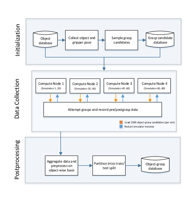
Each simulation consists of three stages: i) pre-processing which includes initializing object parameters and generating grasp candidates, ii) executing a simulation task and collecting data, and iii) postprocessing the collected data. These stages are discussed in depth in Section III, and a general overview is presented in Figure 1.
II-A V-REP simulation environment
The native programming language of V-REP is Lua, and the most direct approach for customizing simulations is to write embedded scripts. These scripts are fully-contained within the simulator, are platform independent, and fully compatible with other V-REP installations [5]. It is also possible to customize through auxiliary methods, such as through add-ons, plugins, various remote APIs or ROS nodes. We chose to use embedded scripts, as development was being done between Windows and Linux environments, and for future work with parallelization allowed us to circumvent additional communication lag or processing overhead.
One of the features of V-REP is that the entire task can be simulated. Grasping is an intermediate operation in an overall robotics task; a simulator that can simulate the entire task starting from perception would be more realistic. This process also includes other factors such as obstacles around the object, as well as reachability and singularity constraints. V-REP supports integrated path-planning and obstacle avoidance modules, as well as inverse kinematics and support for a wide range of manipulators, grippers, and object types.
A variety of sensors (including both tactile and perception) exist within V-REP, and have many different modes of operation (e.g. through infra-red or sonar). There is also a large degree of flexibility in specifying and controlling object properties such as the object’s center of mass, density, or mass itself. Finally, materials in V-REP can also be customized, and properties such as the friction value can be readily specified and changed on a whim. We outline assumptions we made with regard to many of these properties in Table I.
II-B Grasp parameterization and gripper configuration
We assume that all grasps can be parameterized in terms of a specific number of contact points and contact normals . Let be the set of all grasps. Various types of grasps can be simulated using different robotic hands. Both contact positions and normals of the hand’s fingertips are stored. The simulations recorded in the dataset uses the Barrett Hand performing cylindrical precision grasps, but note that the simulator can be used with any multi-fingered hand.
We model the hand as a free-floating entity unattached to any robotic arm, with a proximity sensor attached to the hand’s palm and aligned with the vector normal (i.e. pointing outwards). The proximity sensor serves two purposes: (1) it sets a distance away from the object that the gripper is to be placed, and (2) it permits verification that an object is in the line of sight of the hand. We model the proximity sensor beam as a ray, but note that for interested users, V-REP offers a variety of different modes including: pyramid, disc, cylindrical and conical.
II-C Coordinate frames
Let {O} be the object’s body-attached coordinate frame, {G} be the body-attached coordinate frame on the manipulator’s palm, {W} denote the world coordinate frame, and {T} denote the body-attached coordinate frame of a table top located at = ()
II-D Object representation and properties
We use the object dataset developed by Kleinhans et al. [12], that contains multiple object morphs over a variety of object classes. We use a subset of all available meshes, which were morphed with significant differences between them. Each object has been pre-scaled and saved in the Wavefront .obj file format. Importing the file, we re-mesh, and assume that within V-REP, the object is represented as a Complex shape. The Open Dynamics Engine (ODE) is used for modeling gripper and object dynamics; while ODE was not specifically designed for handling complex shapes, we found our simulation to be fairly stable setting the number of allowable contacts to 64 and setting the configuration to “very accurate”.
The simulator allows assignment of a friction value for each object. A constant friction value was assumed for each object. Furthermore, all objects were assigned the same friction value. We also assumed that each object shared a similar mass of ; while this assumption may not necessarily correspond to real world phenomena (e.g. where larger objects generally correspond to greater mass), it is simple enough to change this to suit a given purpose. Fixing the mass allowed us to make an assumption of the grasp being employed; specifically, that a precision grasp can generate enough force to equalize the object weight and lift the object. We assume partial knowledge of the object’s pose through a crude pose estimation technique (Section III-A), which is employed for generating initial grasp candidates.
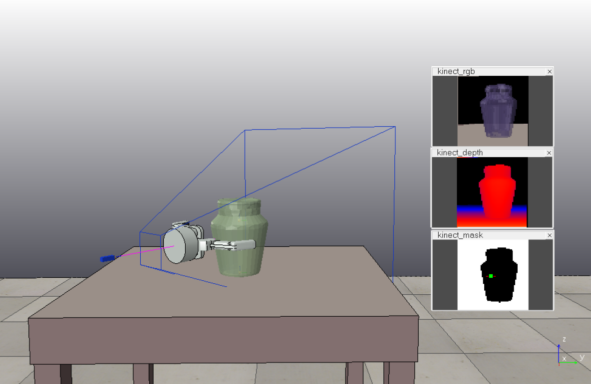
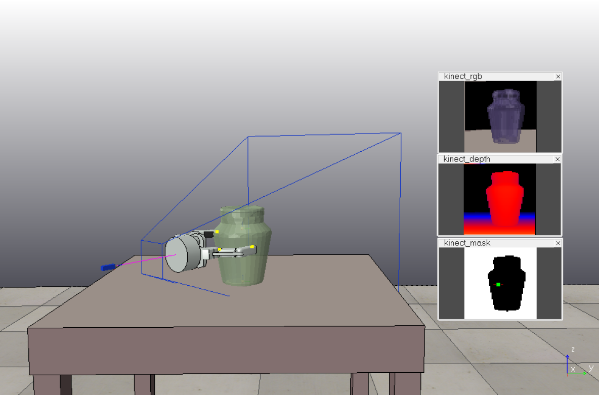
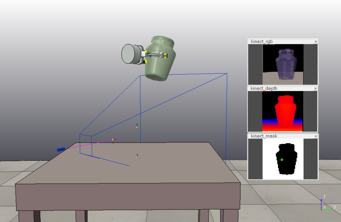
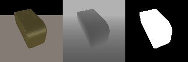
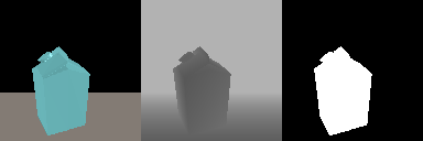
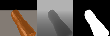
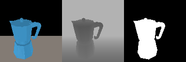
II-E Vision sensors
Two types of vision sensors are present in the scene: (RGB and Depth), as well as a derived Binary mask for performing object segmentation222Note that all vision sensors have an external dependency on OpenGL for rendering.. For our purpose, we assume that each camera can be physically placed coincident with each other such that each of the collected images captures the same amount of information, but through different modalities. In V-REP, we also ensure that each camera only takes a single image (by setting the explicit handling property to true) rather then streaming to avoid unnecessary computation.
Each camera is positioned a distance of along the negative Z-direction of the coordinate frame attached to the hand’s palm, with each camera sharing the same global orientation as the manipulator. In more technical terms, this can be thought of as having a “camera-in-hand” configuration (such as Baxter) and where the approach vector is along this line-of-sight. We use perspective cameras, setting the resolution to be (a modest size for machine learning algorithms), the perspective angle of each camera to be 50∘, and near/far distance clipping planes of 0.01 and respectively.
| Component | Parameter |
|---|---|
| Simulator | V-REP PRO EDU, Version 3.3.0 (rev. 0) |
| Primary language | Lua |
| Dynamics engine | ODE v0.12 |
| Task | Object pick from resting pose on table top |
| Manipulator | Barrett Hand |
| Vision types | RGB-D |
| Object files | Kleinhans et al. [12] |
| Component | Assumption |
| Grasp type | Cylindric precision grasps |
| Grasp candidates | Global and local rotations in object frame |
| Grasp parameterization | Contact normals and positions in object frame |
| Object mass | |
| Object pose | Coarse estimation (Section III-A) |
| Object friction | 0.71 (default; constant among objects) |
| Object geometry | Complex shape |
| Vision perspective angle | |
| Vision position | away from gripper position |
| Vision orientation | Coincident with gripper orientation |
| Vision clipping planes | Near: , Far: |
| Vision resolution | pixels |
III Simulation initialization
Each simulation requires an initial object and hand configuration: object properties need to be defined, and a list of possible grasp candidates needs to be generated.
III-A Initial Object and hand configurations and properties
We begin by preprocessing all object meshes. Each object mesh is loaded into a Python script, which makes use of the trimesh library [4] for ensuring the meshes are watertight, and to obtain an estimate of the objects’ centers of mass and inertia.
Using these preprocessed values, we load each mesh into a V-REP simulation to determine an initial resting pose for the object, and initial pose for a gripper. We begin by assigning a bounding box for the object. This bounding box is used to estimate the object’s pose, by reorienting it with respect to {W}, if not already aligned, and the frame center is assigned to be the geometric center of the object. We then place the object along the positive Z-direction of {T}, and is allowed to fall onto the table. Relative to {T}, the object is then centered at using purely translational components to maintain the resting pose.
Given this resting pose, we then place the gripper at an initial position along the positive Z-direction in {O}. We chose this distance to be away from the object’s center, from the local frame to the bounding box edges along the & directions respectively. All object properties (including object pose, object bounding box, and material) along with the gripper pose are recorded, and this process is repeated for each object in the dataset.
III-B Grasp candidate database
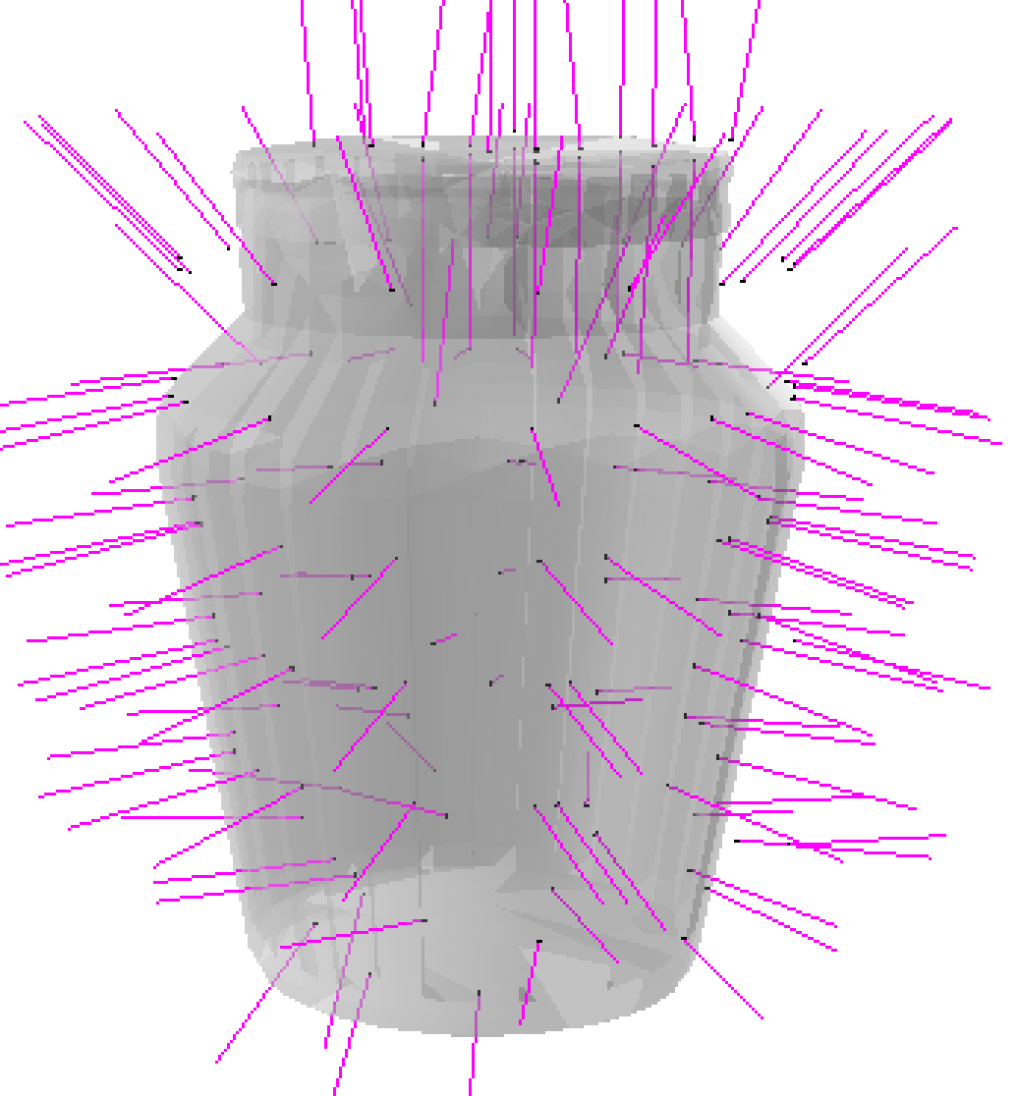
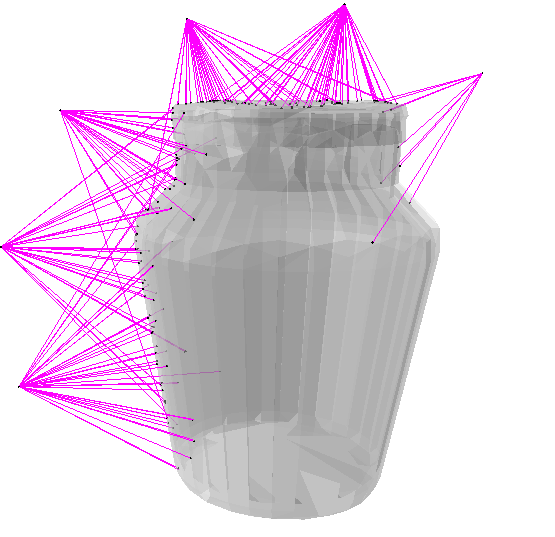
In the grasping literature, a popular method of sampling grasp candidates is through the use of surface normals emanating from the object (e.g. [11],[14]). This has been implemented in simulators such as OpenRAVE [2]. The problem with this approach is that there are several scenarios in which it may not transfer well to the real world. Consider for example the following: (1) sampling candidates from shiny or reflective surfaces (where it is difficult to obtain object surface normals) and (2) sampling from areas with sharp edges and acute angles between adjacent surfaces.
The method used in this simulation to cover the possible grasp candidate space is based on pre- and post-multiplication of the object configuration, which is represented as a transformation matrix. Figure 2 compares the space covered by the proposed technique and a baseline which uses surface normals. It can be seen in this figure that the method of pre- and post-multiplication defines a sampling sphere around the center of the object. While this resolves the above problems, using this method does require an initial estimate of the object’s pose. We estimate the object’s pose according to Section III-A above.
Given the object’s bounding box and gripper pose, we calculate grasp candidates offline by rotating the gripper globally (pre-multiply) and locally (post-multiply) around the object. Following the convention in V-REP [1], we multiply rotation matrices in the order , in the X, Y, and Z axes respectively. Omitting , , and for clarity, the transformation matrix is calculated according to:
| (1) |
where represents the final transformation of the gripper coordinate frame. Computing grasp-candidates is performed offline within a Python script, and uses the estimated bounding box of the object, transformation matrices and 333The complexity of a naïve approach is ; but offline computation allows for grasp candidates to be computed in parallel for each object being considered.. Formally, we exhaustively sample rotations following the constraints in Table II. The constraints were chosen such that 8 rotations would occur around the Z-axes (i.e. every ), and local rotations would occur on a slightly finer scale than the global rotations.
After computing Equation 1, we check whether the new gripper location is beneath the table or not (if so, we reject the grasp candidate), and then solve a system of linear equations to check whether a vector normal from the gripper’s palm intersects with the object’s bounding box. If this intersection is true, we add the grasp candidate to the grasp-candidate database and repeat the process until the list of rotations has been exhausted. Of all the possible candidates in the database, we select up to to be verified in the simulator.
| Rotation | Minimum | Maximum | Increment |
|---|---|---|---|
| Global X | 0 | 180 | 30 |
| Global Y | 0 | 360 | 30 |
| Global Z | 0 | 360 | 45 |
| Local X | 0 | 180 | 20 |
| Local Y | 0 | 360 | 20 |
| Local Z | 0 | 360 | 45 |
via surface normals
IV Simulation procedure
The simulation procedure is illustrated in Figure 3, and begins by loading an object into the simulation, and initializing its mass, inertia, and pose with values recorded during the initialization phase. The object is initially placed into a static state, such that when the fingertips come into contact with the object, the object does not move.
After loading the object, the simulator samples a subset of the potential candidates during the initialization phase (in this work, we use approximately at a time) to test. A large majority of these grasps will be infeasible due to gripper configurations and potential collisions with either the table or object. In cases where this occurs, we stop the current attempt and move to the next candidate.
Each feasible grasp candidate is then checked using the proximity sensor in order to verify the palm is facing the object. If, in this position, the proximity sensor attached to the gripper detects an object, it records the detected surface point and attempts three grasps (using the same gripper orientation) at distances of: away from the detected surface point and along the original palm-normal (Figure 4(a)). These distances were chosen to lie within the distance between the gripper palm and fingertip () for the Barrett Hand, and allow us to explore the geometry of the object at slightly different scales.
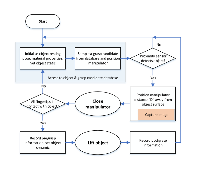
During each of the four attempts, the camera is positioned a distance of away from the hand palm along the local negative Z-direction, and records an image of the object before the grasp is attempted444Computationally, the order the image is taken in is irrelevant; in the real world, the image would be taken before the hand is placed. In V-REP, we can explicitly set the focus of each camera to ignore anything other than the object.. Once the gripper has been placed and an image recorded, the manipulator then closes around the object (Figure 4(b)). If all fingertips are in contact with the object, the object becomes dynamically simulated and the lift procedure begins.
We choose a target lift position of () relative to {T} and force the manipulator to maintain the current grasp pose during travel. Once the gripper has reached the target location, if all fingertips are still in contact with the object, the grasp is deemed stable and a success (Figure 4(c)). This procedure is repeated until the list of grasp candidates has been exhausted. In V-REP, we make use of the Reflexxes Motion Library [13] wrappers (“simRMLxxx” family) for computing the trajectory and for performing incremental steps along the generated path.
IV-A Different image and grasp mappings
As the gripper was programmed to always close around the object in a similar way, we found it interesting to collect two different views of the object during the grasping process:
-
•
Where the orientation of the camera always points upwards (one-to-many mapping), and
-
•
Where the orientation of the camera always matches the orientation of the gripper (one-to-one mapping)
The first point introduces ambiguity into the grasp space, by evoking a one-to-many mapping between images and grasps. In this case, the gripper orientation is not directly linked to the camera orientation, which means that a single image may correspond to possibly many different grasps. The second point, however, introduces a more direct relationship between images and grasps; similar orientations of the object captured in the image reflect similar orientations within the grasp. We have split this phenomenon into two separate files for convenience.
IV-B Parallelization
Because such a large number of grasp candidates are sampled, and the number of objects to be evaluated is relatively high, in order to create the dataset within a feasible amount of time some form of parallelization is required.
The University of Guelph has a compute cluster consisting of 10 nodes, with each node containing multiple Nvidia TITAN X GPUs and 2 Intel Xeon E5–2620 CPUs running at 2.10GHz. Each CPU has 6 cores, and with hyperthreading gives us access to 24 virtual cores and 64GB RAM. Using the grasp candidates sampled offline, as described in Section III-B, we evenly distribute the load across 4 compute nodes with 80 simulations running in parallel. We use GNU Parallel for managing the load on each node [24].
We operate each scene in headless mode (i.e. running without any graphical interface), under an Xorg server due to requirements from the vision sensors which require a small amount of memory from the graphics cards. In our simulation, each scene typically uses around 4MiB, and for the Xorg server around 20MiB. In total, we use slightly more than 100MiB of the graphics card for running 20 simulations concurrently and have found this process to take between 10–14 days to fully complete.
V Postprocessing
Once all simulations have finished running, we apply a postprocessing step to clean and standardize the collected data. This step consists of three parts: i) decoding collected depth images, ii) automatic removal of grasp outliers, and iii) manual inspection and final removal, which are performed before constructing the dataset.
V-A Decoding depth images
Within the simulation, information captured via a depth buffer is encoded to a range between , and can be decoded to real-world values by applying:
| (2) |
where is the collected image, and , are the near and far clipping planes respectively. Because some of the images can be quite large, and depending on the view of the objects that the cameras have, they may yield no useful shape information. In these instances, the object typically occupies the full sensor resolution, and no edges are visible. To combat this, we remove all object-grasp instance pairs where the image variance is less then . We also remove any grasps where the collected image appears to bisect the table, which occurs when the camera height matches that of the table height. Depth information encoded in this scenario is often at a minimum.
V-B Postprocessing outliers
When removing grasp outliers, we consider objects individually, and remove any object-grasp instance pairs where one of the variables (either a fingertip position or a normal) falls outside of 4 standard deviations of the population mean. While on the surface a very simple method, we have found it to perform quite well in removing some of the more unlikely grasps, and reducing the number of grasps that will receive manual attention in the following step.
V-C Manual removal of physically inaccurate grasps
We have noticed that grasps that make it through automatic filtering can often be related to the complexity of the associated object mesh. Part of this is linked to an earlier assumption that was made: specifically, that all meshes can be simulated accurately within the environment as complex objects. However, all objects are not created equal.
Objects with a greater number of faces, or those composed of several different components have an (understandably) more difficult time within the simulator. In addition to these difficulties, there are subtle cases where one of the fingertips contacts an edge of the object. When this contact occurs, it is possible that an improper contact normal may be retrieved during a dynamics pass within the simulation. In all cases, we remove those grasps which we perceive as physically impossible.
Once this is done, we consider all the objects for a given class, and remove one to place into a test. From the remaining objects, we randomly sample 10% of all grasps to place into a validation set, while the remaining grasps comprise the training set. We only populate the training, testing, and validation sets with successful grasps.


VI Dataset
The code for this project can be accessed at https://github.com/mveres01/grasping, while a sample dataset can be accessed at http://dx.doi.org/10.5683/SP/KL5P5S. The dataset has been saved in the HDF5 format, and was created using Python. While the postprocessing step removes most abnormal grasps, note that there may be a select few that remain physically inaccurate. Therefore the dataset is not without some noise. The statistics for each of the training, testing, and validation sets are reported in Table III.
| Element | # Samples | # Object classes |
|---|---|---|
| Train | 32,100 | 20 |
| Validation | 3,564 | 20 |
| Test | 14,693 | 62 |
VI-A Dataset overview
Within each data split, there are three serialized data structures: images, grasps, and object properties that help describe the current state of the simulation and grasp process.
mages :~a 4-d array of mages, in the format: (samples, channels, rows,
cols), where channels is composed of RGB-D elements.
rasps :~a 2-d matrix of rasps : (samples, grasp), encoded with respect
to the camera frame. Each grasp is encoded as the 18-dimensional vector , where is the (x,
y, z) position of finger and is the (x, y, z) vector normal of finger
.
VI-B Description of frames
All frames are encoded as a homogeneous transformation matrix. We leave it to the user to format these as proper homogeneous transform matrices by reshaping each matrix to be of shape , then adding the row vector . Table IV outlines the frames of reference saved during data collection; note that “workspace” corresponds to the frame {T} above.
| Frame | Description |
|---|---|
rame_cam2img_otm & estimated image rame with respect to camera frame |
|
rame_cam2work_otm & {workspace rame with respect to camera frame,
one-to-many mapping |
|
rame_cam2work_oto & {workspace rame with respect to camera frame,
one-to-one mapping |
|
rame_work2cam_otm & {camera rame with respect to workspace frame,
one-to-many mapping |
|
rame_work2cam_oto & {camera rame with respect to workspace frame,
one-to-one mapping |
|
rame_world2obj & object’s (physical) reerence frame with respect to world frame |
|
rame_world2work & workspace rame (i.e. center of the table top) with respect to world frame |
VI-C Description of object properties
Several object-specific properties were also captured. These are summarized in Table V.
| Property | Description |
|---|---|
bject_name & name f the object |
|
ork2com & {location of the object’s center of mass ith respect to workspace frame |
|
ork2inertia & {object’s inertia ith respect to workspace frame |
|
ork2mass & {object’s mass ith respect to workspace frame |
The object’s center of mass is a vector, inertia is a vector, and mass is a single scalar.
VII Conclusion
In this paper, we presented an integrated system for collecting cylindrical precision robotic grasps using the Barrett Hand and V-REP simulator. We demonstrated an approach for computing grasp candidates using local and global rotations around an object-centric reference frame, and presented our experience managing large-scale data collection over multiple compute nodes. It is our hope that other individuals are able to use these ideas in their own implementations.
Acknowledgment
The authors would like to thank Brian Tripp and Ashley Kleinhans from the University of Waterloo for early access to the object models in this paper, as well as for discussion on specific design choices in a simulation similar to ours. The authors would also like to thank Marc Freese from Coppelia Robotics for technical support surrounding operation of the V-REP simulator.
References
- [1] “Euler angles,” http://www.coppeliarobotics.com/helpFiles/en/eulerAngles.htm, accessed: 2016-06-02.
- [2] “Openrave documentation, grasping module,” http://openrave.org/docs/0.6.6/openravepy/databases.grasping/, accessed: 2016-03-21.
- [3] “Scipy.optimize,” http://docs.scipy.org/doc/scipy/reference/optimize.minimize-slsqp.html, accessed: 2016-06-03.
- [4] “trimesh 2.5.33,” https://pypi.python.org/pypi/trimesh, accessed: 2017-01-26.
- [5] “Writing code in and around v-rep,” http://www.coppeliarobotics.com/helpFiles/en/writingCode.htm, accessed: 2016-06-02.
- [6] J. Bohg, A. Morales, T. Asfour, and D. Kragic, “Data-driven grasp synthesis—a survey,” Robotics, IEEE Transactions on, vol. 30, no. 2, pp. 289–309, 2014.
- [7] coppelia, “Inverse Kinematics For Barrett Hand - V-REP Forum,” 2016, accessed 2017-01-23. [Online]. Available: http://www.forum.coppeliarobotics.com/viewtopic.php?f=9&t=5263
- [8] R. Diankov, “Automated construction of robotic manipulation programs,” Ph.D. dissertation, Carnegie Mellon University, Robotics Institute, August 2010. [Online]. Available: http://www.programmingvision.com/rosen_diankov_thesis.pdf
- [9] T. Erez, Y. Tassa, and E. Todorov, “Simulation tools for model-based robotics: Comparison of bullet, havok, mujoco, ode and physx,” in Robotics and Automation (ICRA), 2015 IEEE International Conference on. IEEE, 2015, pp. 4397–4404.
- [10] S. Ivaldi, V. Padois, and F. Nori, “Tools for dynamics simulation of robots: a survey based on user feedback,” arXiv preprint arXiv:1402.7050, 2014.
- [11] D. Kappler, J. Bohg, and S. Schaal, “Leveraging big data for grasp planning,” in IEEE International Conference on Robotics and Automation, May 2015.
- [12] A. Kleinhans et al., “G3DB: a database of successful and failed grasps with RGB-D images, point clouds, mesh models and gripper parameters,” in International Conference on Robotics and Automation: Workshop on Robotic Grasping and Manipulation, 2015.
- [13] T. Kröger, “Opening the door to new sensor-based robot applications—the reflexxes motion libraries,” in Robotics and Automation (ICRA), 2011 IEEE International Conference on. IEEE, 2011, pp. 1–4.
- [14] I. Lenz, H. Lee, and A. Saxena, “Deep learning for detecting robotic grasps,” The International Journal of Robotics Research, vol. 34, no. 4-5, pp. 705–724, 2015.
- [15] S. Levine, P. Pastor, A. Krizhevsky, and D. Quillen, “Learning hand-eye coordination for robotic grasping with deep learning and large-scale data collection,” International Symposium on Experimental Robotics, 2016.
- [16] J. Mahler et al., “Dex-Net 1.0: A cloud-based network of 3d objects for robust grasp planning using a multi-armed bandit model with correlated rewards,” in IEEE International Conference on Robotics and Automation, May 2016.
- [17] A. T. Miller and P. K. Allen, “Graspit! a versatile simulator for robotic grasping,” Robotics & Automation Magazine, IEEE, vol. 11, no. 4, pp. 110–122, 2004.
- [18] M. A. Moussa and M. S. Kamel, “An experimental approach to robotic grasping using a connectionist architecture and generic grasping functions,” IEEE Transactions on Systems, Man, and Cybernetics, Part C (Applications and Reviews), vol. 28, no. 2, pp. 239–253, 1998.
- [19] L. Pinto and A. Gupta, “Supersizing self-supervision: Learning to grasp from 50k tries and 700 robot hours,” in IEEE International Conference on Robotics and Automation, May 2016.
- [20] M. Quigley, J. Faust, T. Foote, and J. Leibs, “Ros: an open-source robot operating system.”
- [21] E. Rohmer, S. P. N. Singh, and M. Freese, “V-REP: A versatile and scalable robot simulation framework,” in IEEE/RSJ International Conference on Intelligent Robots and Systems, 2013.
- [22] A. Sahbani, S. El-Khoury, and P. Bidaud, “An overview of 3d object grasp synthesis algorithms,” Robotics and Autonomous Systems, vol. 60, no. 3, pp. 326–336, 2012.
- [23] R. Suárez, M. Roa, and J. Cornella, Grasp quality measures. Tech. Univ. Catalonia, Barcelonia, Spain, 2006, vol. IOC-DT-P-2006-10.
- [24] O. Tange, “Gnu parallel - the command-line power tool,” ;login: The USENIX Magazine, vol. 36, no. 1, pp. 42–47, Feb 2011. [Online]. Available: http://www.gnu.org/s/parallel
- [25] M. Veres, M. Moussa, and G. W. Taylor, “Modeling grasp motor imagery through deep conditional generative models,” IEEE Robotics and Automation Letters, vol. 2, no. 2, pp. 757–764, April 2017.
-A A note on verifying grasps
In this work, we used the 18-dimensional vector containing contact positions and normals to represent a grasp. In order to test predicted grasps within a simulator, there are two potential options: Applying forces directly to the object, or finding an optimal wrist pose and solving a series of inverse kinematic equations to find the finger joint angles.
-A1 Applying forces directly
V-REP has the capability for applying arbitrary forces to an object (e.g. via the simAddForce function), which allows the user to circumvent the use of a robotic hand. This is likely the most direct method for implementing into the current simulation, and would require swapping the hand module for a module that reads in a set of contact positions and normals, and applies them accordingly.
-A2 Solving inverse kinematics
In order to take advantage of the inverse kinematics modules within V-REP for positioning the fingertips, a little help is needed to find the initial pose of the manipulators wrist. This can be done by solving a series of linear equations, making use of the Sequential Least Squares Programming implementation in SciPy [3].
Formally, we solve for an initial wrist position by optimizing the rotational and translation components of the matrix , minimizing the following objective function [7]:
where are the x, y, and z rotational components, , , are the x,y, and z are the translational components, is the number of fingertips, are the fingertip positions with respect to {O} (obtained by multiplying with forward kinematics to the manipulator’s fingertips), and is the predicted fingertip positions with respect to {O}.