Double-sided coaxial circuit QED with out-of-plane wiring
Abstract
Superconducting circuits are well established as a strong candidate platform for the development of quantum computing. In order to advance to a practically useful level, architectures are needed which combine arrays of many qubits with selective qubit control and readout, without compromising on coherence. Here we present a coaxial circuit QED architecture in which qubit and resonator are fabricated on opposing sides of a single chip, and control and readout wiring are provided by coaxial wiring running perpendicular to the chip plane. We present characterization measurements of a fabricated device in good agreement with simulated parameters and demonstrating energy relaxation and dephasing times of s and s respectively. The architecture allows for scaling to large arrays of selectively controlled and measured qubits with the advantage of all wiring being out of the plane.
The realization of technological devices that harness quantum superposition and entanglement to perform computational tasks that are difficult with classical computers is a major research goal that may revolutionize computingLadd et al. (2010). Superconducting circuits have advanced to become a strong candidate platform for building such quantum computersDevoret and Schoelkopf (2013), with recent demonstrations of circuit operation at the threshold for fault toleranceBarends et al. (2014), quantum error detectionRistè et al. (2015); Kelly et al. (2015) and correctionOfek et al. (2016), and rudimentary quantum simulationsSalathé et al. (2015); Barends et al. (2015); O’Malley et al. (2016). While the scale required for full fault tolerant universal quantum computation is still far awayFowler et al. (2012), current devices are not far from the complexity required for a demonstration of computation that is beyond the reach of the best classical supercomputersBoixo et al. (2016). To reach beyond this scale (of order 50 qubits) in a single monolithic quantum circuit, it is desirable to develop circuit architectures that implement good connectivity among arrays of many qubits, along with selective control and readout wiring, without compromising on qubit coherence. This is difficult to achieve if the circuit is constrained to a single 2D plane, since the number of control and readout connections scales linearly with the number of qubits , while the edges of a 2D array scale as . This problem can only be overcome by incorporating 3D connectivity.
The challenge of incorporating control wiring out of the plane of a superconducting quantum circuit has been approached so far from several directions. A recent proposal suggests the use of through-chip microwave silicon vias, as part of a monolithic architecture to implement the surface code Versluis et al. (2016). Bump bonding between multiple circuit layers Mutus et al. (2017), and spring-loaded microwave contacts Béjanin et al. (2016) are also under development. Pursuing a modular (as opposed to monolithic) quantum computing architecture is an alternative route, and some promising steps have been made in this direction with superconducting circuits, through integration with high quality 3D microwave resonators Axline et al. (2016); Brecht et al. (2016); Narla et al. (2016).
In this letter we present a single unit cell of an architecture for quantum computing with superconducting circuits that is simple to fabricate, requires no bonds, exploits only capacitive couplings, and implements qubit control and readout entirely out of the plane of the qubit, without relying on complex through-chip fabricationTolpygo (2016).
By virtue of the out-of-plane readout and wiring elements the device may be physically scaled to large 2D qubit arrays without any alteration to the wiring design. Additionally the double-sided structure and absence of wiring elements in the circuit design avoids crowding on the chip, hence reducing sources of crosstalk.
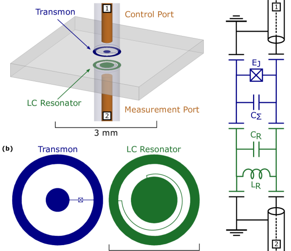
The device is depicted in Fig. 1. It consists of a superconducting charge qubit in the transmon regimeKoch et al. (2007) with coaxial electrodes, which we call the coaxmon (similar to the concentric Braumüller et al. (2016) and apertureBrecht et al. (2016) transmons) coupled to a lumped element LC microwave resonator fabricated on the opposite side of the chip, realising dispersive circuit quantum electrodynamicsWallraff et al. (2004) (QED). The device is controlled and measured via coaxial ports, perpendicular to the plane of the chip (see Fig. 1 (a)), whose distance from the chip can be modified to change the external quality factor of the circuits. These ports can be used for independent control of the qubit and measurement of the resonator in reflection, or to measure the device in transmission.
The device is fabricated through two stages of electron beam lithography, patterning either side of a mm thick sapphire chip with an aluminum LC resonator and coaxmon. During fabrication the bottom of the chip is protected with a spin-coated layer of polymer resist, and chip holders are used to ensure the bottom of the device is suspended throughout. The process could be further improved in the future by producing the LC resonators with photolithography thus enabling batch production of devices that only require one electron-beam step. The device is then mounted in an aluminum sample holder and thermally anchored to the mK base plate of a dilution refrigerator. The control and measurement ports consist of copper-beryllium wire passing through a cylindrical hole in the sample holder, soldered to the center conductor of a microwave connector in order to connect to external microwave wiring. In this experiment the distance from the qubit(resonator) to the control(measurement) port is mm. The device is embedded in a standard circuit QED measurement setup, in which input signals are heavily cryogenically attenuated (by approximately dB) to reduce thermal noise, and measurements are made via cryogenic circulators and a low noise HEMT amplifier, the signal finally being recorded as a voltage with an analog-to-digital converter (ADC).
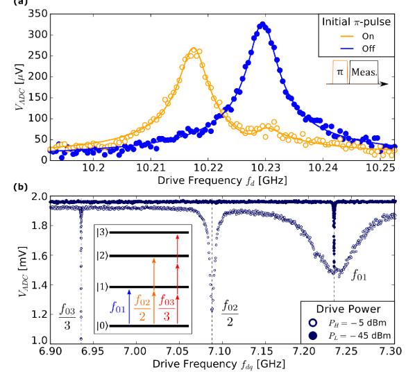
We first measure the device transmission spectrum at a low drive power of dBm, finding the Lorentzian response of the LC resonatorsampleholder at GHz, with quality factor (see Fig. 2 (a)). Far from resonance, remains dB below the LC resonance over the GHz measurement bandwidth. We next fix the measurement drive at the LC resonance, and add an additional drive at frequency to port 1, to carry out spectroscopy of the qubit using the dispersive qubit state-dependent frequency shift of the LC resonator Wallraff et al. (2005). The spectroscopy is carried out with an s drive pulse immediately followed by an s measurement pulse at frequency and power dBm, averaging the data times. In Fig. 2 (b) we show such spectroscopy at two different drive powers. At low drive power we observe only the qubit transition at , whereas at higher power we observe two additional spectral lines below , as expected of a transmon qubit. We observe a two-photon transition at and a three-photon transition at to higher energy levels of the transmon, as illustrated in the inset of Fig. 2 (b). Note that the broadening of the peak at the higher drive power originates from strong Rabi driving of the transition. From these parameters we calculate a detuning between qubit and resonator of GHz, Josephson energy GHz, charging energy MHz, and .
We next characterize the interaction between qubit and resonator by measuring the qubit-state-dependent resonator frequency shift . In order to do this, we repeat the transmission measurement of the LC resonance after preparing the qubit in its first excited state prior to a measurement pulse (see Fig. 2 (a) orange curve). The resonance is seen to shift from to GHz. In addition to the shifted peak at , a residual peak at is also visible due to the excited state population partly decaying during the measurement pulse. The response is fitted to the weighted sum of two Lorentzians in the complex plane, from which we extract the dispersive shift of the resonator MHz. We then use this to derive the qubit-resonator coupling MHz from the relation
| (1) |
valid for a transmon in the dispersive regimeKoch et al. (2007). Since our implementation of cQED consists entirely of lumped elements, we can calculate the expected parameters using a finite element electrostatic simulation (Ansys Maxwell) of the circuit. The circuit representation can be quantized to give expressions for the qubit and resonator frequencies, and , and the coupling between them, as a function of the capacitance network, as well as the resonator inductance and Josephson energy which we match to the experimentally measured values. Such a simulation predicts a coupling MHz. The discrepancy between the estimated and measured value may be due to the use of a static solver, which neglects any inductive coupling in the circuit. We have also used this model to simulate the coupling between control (measurement) port and qubit (resonator), and its dependence on the displacement of the port axis from the qubit and resonator centers. We find that for the circuit geometry presented here, the coupling falls to at a displacement of 1 mm, indicating that good selectivity should be achievable between control and measurement signals in adjacent cells in a grid of multiple qubits.
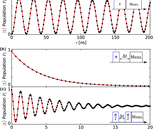
We now move on to time resolved qubit measurements which are performed by measuring the resonator in reflection on port 2 and applying qubit drive pulses to port 1. In Fig 3 (a) we first show Rabi oscillations of the qubit state, measured by first applying a short microwave pulse of length to the qubit in its ground state at frequency , followed by a resonator readout pulse of length 16 s and frequency at a low photon number. The population of the qubit excited state is recovered from the weighted integral of the resonator response by comparing it to the integral of simulated Cavity-Bloch tracesBianchetti et al. (2009) using parameters independently determined by the other characterization experiments, and including a correction to take into account interference with the directly reflected measurement pulse.
We determine the qubit relaxation time s and phase coherence time s using standard techniques (see Fig. 3 (b) and (c)). A spin echo pulse sequence reveals an extended s. To further evaluate the performance of the device we perform Clifford-based randomized benchmarking and find the average fidelities of primitive gates to be 99.5% using half-DRAG pulsesLucero et al. (2010). We also determine an upper bound for the qubit temperature by measuring the amplitude of Rabi oscillations on the transition both with and without an initial -pulse on the transitionGeerlings et al. (2013). We find the qubit temperature to be mK corresponding to an initial ground state population of . Hence our single-qubit unit cell displays promising performance for an initial demonstration.
| Parameter | Value |
|---|---|
| Resonator Frequency [GHz] | 10.23 |
| Resonator Quality Factor | 2080 |
| Qubit [GHz] | 7.23 |
| Dispersive shift [MHz] | -6.34 |
| [MHz] | 294 |
| 81.8 | |
| Coupling [MHz] | 462 |
| [s] | 4.10 |
| [s] | 5.65 |
| Echo [s] | 6.67 |
We have presented a double-sided coaxial implementation of circuit QED. We summarize the device parameters in table 1. We anticipate this architecture to be easily extendable to arrays of nearest-neighbor coupled qubits by virtue of the out-of-plane readout and control wiring, and so will be a good candidate architecture for the next generation of multi-qubit devices for quantum simulation and computation.
I Acknowledgments
This work has received funding from the UK Engineering and Physical Sciences Research Council under grants EP/J001821/1, EP/J013501/1 and EP/M013243/1. AP and TT acknowledge Oxford Instruments Nanoscience and the Nakajima Foundation respectively for financial support. Aspects of this work are currently covered by an international patent application.
References
- Ladd et al. (2010) T. D. Ladd, F. Jelezko, R. Laflamme, Y. Nakamura, C. Monroe, and J. L. O’Brien, Nature 464, 45–53 (2010).
- Devoret and Schoelkopf (2013) M. H. Devoret and R. J. Schoelkopf, Science 339, 1169–1174 (2013).
- Barends et al. (2014) R. Barends, J. Kelly, A. Megrant, A. Veitia, D. Sank, E. Jeffrey, T. C. White, J. Mutus, A. G. Fowler, B. Campbell, Y. Chen, Z. Chen, B. Chiaro, A. Dunsworth, C. Neill, P. O’Malley, P. Roushan, A. Vainsencher, J. Wenner, A. N. Korotkov, A. N. Cleland, and J. M. Martinis, Nature 508, 500–503 (2014).
- Ristè et al. (2015) D. Ristè, S. Poletto, M. Z. Huang, A. Bruno, V. Vesterinen, O. P. Saira, and L. DiCarlo, Nature Communications 6, 6983 (2015).
- Kelly et al. (2015) J. Kelly, R. Barends, A. G. Fowler, A. Megrant, E. Jeffrey, T. C. White, D. Sank, J. Y. Mutus, B. Campbell, Y. Chen, Z. Chen, B. Chiaro, A. Dunsworth, I. C. Hoi, C. Neill, P. J. J. O’Malley, C. Quintana, P. Roushan, A. Vainsencher, J. Wenner, A. N. Cleland, and J. M. Martinis, Nature 519, 66–69 (2015).
- Ofek et al. (2016) N. Ofek, A. Petrenko, R. Heeres, P. Reinhold, Z. Leghtas, B. Vlastakis, Y. Liu, L. Frunzio, S. M. Girvin, L. Jiang, M. Mirrahimi, M. H. Devoret, and R. J. Schoelkopf, Nature 536, 441–445 (2016).
- Salathé et al. (2015) Y. Salathé, M. Mondal, M. Oppliger, J. Heinsoo, P. Kurpiers, A. Potočnik, A. Mezzacapo, U. Las Heras, L. Lamata, E. Solano, S. Filipp, and A. Wallraff, Phys. Rev. X 5, 021027 (2015).
- Barends et al. (2015) R. Barends, L. Lamata, J. Kelly, L. García-Álvarez, A. G. Fowler, A. Megrant, E. Jeffrey, T. C. White, D. Sank, J. Y. Mutus, B. Campbell, Y. Chen, Z. Chen, B. Chiaro, A. Dunsworth, I. C. Hoi, C. Neill, P. J. J. O’Malley, C. Quintana, P. Roushan, A. Vainsencher, J. Wenner, E. Solano, and J. M. Martinis, Nature Communications 6, 7654 (2015).
- O’Malley et al. (2016) P. J. J. O’Malley, R. Babbush, I. D. Kivlichan, J. Romero, J. R. McClean, R. Barends, J. Kelly, P. Roushan, A. Tranter, N. Ding, B. Campbell, Y. Chen, Z. Chen, B. Chiaro, A. Dunsworth, A. G. Fowler, E. Jeffrey, E. Lucero, A. Megrant, J. Y. Mutus, M. Neeley, C. Neill, C. Quintana, D. Sank, A. Vainsencher, J. Wenner, T. C. White, P. V. Coveney, P. J. Love, H. Neven, A. Aspuru-Guzik, and J. M. Martinis, Phys. Rev. X 6, 031007 (2016).
- Fowler et al. (2012) A. G. Fowler, M. Mariantoni, J. M. Martinis, and A. N. Cleland, Phys. Rev. A 86, 032324 (2012).
- Boixo et al. (2016) S. Boixo, S. V. Isakov, V. N. Smelyanskiy, R. Babbush, N. Ding, Z. Jiang, J. M. Martinis, and H. Neven, e-print arXiv:1608.00263 (2016).
- Versluis et al. (2016) R. Versluis, S. Poletto, N. Khammassi, N. Haider, D. J. Michalak, A. Bruno, K. Bertels, and L. DiCarlo, e-print arXiv:1612.08208 (2016).
- Mutus et al. (2017) J. Mutus, B. Foxen, E. Lucero, J. Kelly, Y. Yang, A. Yu, M. Baldwinson, Z. Chen, B. Chiaro, A. Dunsworth, C. Neill, C. Quintana, J. Wenner, and J. M. Martinis, H46.00006: APS March Meeting (2017).
- Béjanin et al. (2016) J. H. Béjanin, T. G. McConkey, J. R. Rinehart, C. T. Earnest, C. R. H. McRae, D. Shiri, J. D. Bateman, Y. Rohanizadegan, B. Penava, P. Breul, S. Royak, M. Zapatka, A. G. Fowler, and M. Mariantoni, Phys. Rev. Applied 6, 044010 (2016).
- Axline et al. (2016) C. Axline, M. Reagor, R. Heeres, P. Reinhold, C. Wang, K. Shain, W. Pfaff, Y. Chu, L. Frunzio, and R. J. Schoelkopf, Appl. Phys. Lett. 109, 042601 (2016).
- Brecht et al. (2016) T. Brecht, Y. Chu, C. Axline, W. Pfaff, J. Z. Blumoff, K. Chou, L. Krayzman, L. Frunzio, and R. J. Schoelkopf, Phys. Rev. Applied 7, 044018 (2017).
- Narla et al. (2016) A. Narla, S. Shankar, M. Hatridge, Z. Leghtas, K. M. Sliwa, E. Zalys-Geller, S. O. Mundhada, W. Pfaff, L. Frunzio, R. J. Schoelkopf, and M. H. Devoret, Phys. Rev. X 6, 031036 (2016).
- Tolpygo (2016) S. K. Tolpygo, Low Temperature Physics 42, 361–379 (2016).
- Koch et al. (2007) J. Koch, T. M. Yu, J. Gambetta, A. A. Houck, D. I. Schuster, J. Majer, A. Blais, M. H. Devoret, S. M. Girvin, and R. J. Schoelkopf, Phys. Rev. A 76, 042319 (2007).
- Braumüller et al. (2016) J. Braumüller, M. Sandberg, M. R. Vissers, A. Schneider, S. Schlör, L. Grünhaupt, H. Rotzinger, M. Marthaler, A. Lukashenko, A. Dieter, A. V. Ustinov, M. Weides, and D. P. Pappas, Appl. Phys. Lett. 108, 032601 (2016).
- Wallraff et al. (2004) A. Wallraff, D. I. Schuster, A. Blais, L. Frunzio, R.-S. Huang, J. Majer, S. Kumar, S. M. Girvin, and R. J. Schoelkopf, Nature 431, 162–167 (2004).
- (22) In order to rule out the possibility that this resonance is a mode of the sample holder, we have performed high frequency simulations of the device predicting the LC resonance at GHz and the lowest frequency mode of the sample holder at GHz .
- Wallraff et al. (2005) A. Wallraff, D. I. Schuster, A. Blais, L. Frunzio, J. Majer, M. H. Devoret, S. M. Girvin, and R. J. Schoelkopf, Phys. Rev. Lett. 95, 060501 (2005).
- Bianchetti et al. (2009) R. Bianchetti, S. Filipp, M. Baur, J. M. Fink, M. Göppl, P. J. Leek, L. Steffen, A. Blais, and A. Wallraff, Phys. Rev. A 80, 043840 (2009).
- Lucero et al. (2010) E. Lucero, J. Kelly, R. C. Bialczak, M. Lenander, M. Mariantoni, M. Neeley, A. D. O’Connell, D. Sank, H. Wang, M. Weides, J. Wenner, T. Yamamoto, A. N. Cleland, and J. M. Martinis, Phys. Rev. A 82, 042339 (2010).
- Geerlings et al. (2013) K. Geerlings, Z. Leghtas, I. M. Pop, S. Shankar, L. Frunzio, R. J. Schoelkopf, M. Mirrahimi, and M. H. Devoret, Phys. Rev. Lett. 110, 120501 (2013).