Incoherence-Mediated Remote Synchronization
Abstract
In previously identified forms of remote synchronization between two nodes, the intermediate portion of the network connecting the two nodes is not synchronized with them but generally exhibits some coherent dynamics. Here we report on a network phenomenon we call incoherence-mediated remote synchronization (IMRS), in which two non-contiguous parts of the network are identically synchronized while the dynamics of the intermediate part is statistically and information-theoretically incoherent. We identify mirror symmetry in the network structure as a mechanism allowing for such behavior, and show that IMRS is robust against dynamical noise as well as against parameter changes. IMRS may underlie neuronal information processing and potentially lead to network solutions for encryption key distribution and secure communication.
Published in Phys. Rev. Lett. 118, 174102 (2017)
Communication, broadly defined as information exchange between different parts of a system, is a fundamental process through which collective dynamics arises in complex systems. Network synchronization Pikovsky2003 , whether it is complete synchrony syn5 or a more general form of synchronization Kaneko:1990 ; Stewart:2003 ; cluster2 ; cluster1 ; pecora , is a primary example of such dynamics and is thought to be largely driven by node-to-node communication. However, it has recently been shown that so-called remote synchronization Winful:1990 ; Fischer:2006 ; Sande2008 ; Soriano2012 ; Bergner:2012 ; Viriyopase:2012 ; remote2 ; Gambuzza:2013 is possible: two distant nodes (or groups of nodes) can synchronize even when the intermediate nodes are not synchronized with them. In this form of synchronization, the dynamics of different intermediate nodes generally show some level of coherence with each other, exhibiting, e.g., generalized synchronization or delay synchronization.
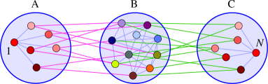
In contrast, in this Letter we consider a dynamical state of a network that we shall call incoherence-mediated remote synchronization (IMRS). The nodes of the network are organized into three non-empty groups, A, B, and C, where A is connected with B, and B is connected with C, but A and C are not directly connected (as illustrated in Fig. 1). We assume that group B has at least two nodes, and that the nodes and links within each group form a connected subnetwork. IMRS is then characterized by (1) a node from group A (denoted node ) and a node from C (denoted node ) that are identically synchronized (rather than in weaker forms such as phase and generalized synchronization), and (2) the dynamics of the nodes in the intermediate group B that are statistically incoherent with each other. IMRS combines the properties of remote synchronization mentioned above with those of chimera states Kuramoto:2002 ; Abrams:2004 ; pecora1 ; Tinsley:2012 ; Panaggio:2015 , which are characterized by the coexistence of both coherent and incoherent dynamics in different parts of the network. Here, however, we lift the assumption of uniform network typically made in studying chimera states, and instead ask the following fundamental question: under what conditions can IMRS be observed? In particular, what types of network structure allow for this behavior? Below we answer these questions by mapping them to the problem of cluster synchronization and using a powerful tool for studying network symmetry based on computational group theory pecora . Moreover, we show that the incoherent dynamics of group B is typically also incoherent relative to the dynamics of node (and ). This suggests applications of IMRS to new forms of secure communication technologies Cuomo:1993 ; Argyris:2005 or new schemes for secure generation and distribution of encryption keys hayato .
We consider a general class of networks of coupled identical dynamical units, whose time evolution is governed by
| (1) |
where is the state of the th unit at time , the equation describes the dynamics of an isolated node, is the overall coupling strength, is the coupling matrix representing an undirected unweighted network topology of the type illustrated in Fig. 1, and is a function determining the output signal from a node. Within this framework, we formulate a set of three conditions for IMRS to be observed:
-
(i)
There exists a state in which for .
-
(ii)
The state of synchronization between nodes and in condition (i) is stable.
-
(iii)
and are not synchronized for all node pairs and are statistically incoherent for most pairs in B.
(Recall that nodes and are from groups A and C, respectively.)
Although condition (i) is dynamical in nature, a network-structural condition implying condition (i) can be expressed solely in term of the symmetry of the network. The network symmetry is represented by the (mathematical) group of node permutations under which the network structure is invariant (or, equivalently, the group consisting of the corresponding permutation matrices that commute with the adjacency matrix ). A cluster of synchronized nodes can be identified as an orbit of this group, defined as a set of nodes in which each node can be mapped to any other nodes in the set by some permutation in the group. From the invariance of Eq. (1) under these permutations, it follows that there is a synchronous state in which all nodes in each orbit (of the group) have identical dynamics, forming clusters: , where for all if node belongs to cluster . Note that can be different for different as long as they satisfy the equations obtained by substituting into Eq. (1). Formulating IMRS as such a state, we see that condition (i) above is equivalent to the existence of an orbit that intersects with both A and C. We denote this cluster by , from which we choose one node in A as node , and one node in C as node .
The synchronization stability condition (ii) is verified for a given network structure using the method in Ref. pecora . We first identify clusters in the network using computational group theory. We then compute , the maximum transverse Lyapunov exponent associated with the modes of perturbation that destroys the synchronization of cluster (some of which destroy the synchronization between nodes and ). Thus, condition (ii) can be formulated as .
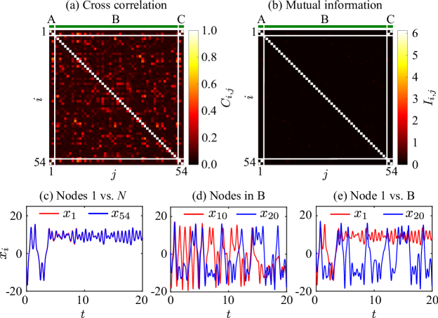
The statistical coherence in condition (iii) is measured by cross correlation and mutual information, accounting for possible coherence with a time lag . We use to denote the absolute value of the Pearson correlation coefficient between and over a range of , maximized over a range of timedelay1 . Likewise, we use to denote the mutual information between and over , maximized over timedelay1 ; mi1 . Thus, condition (iii) would be satisfied if and are both small for most pairs and in B, and for (indicating no identical synchronization). We choose chaotic node dynamics for higher likelihood of having incoherence in B, and we further ensure that the dynamics of is chaotic. This condition is equivalent to , where is the maximum Lyapunov exponent parallel to the synchronization manifold (associated with perturbations that do not destroy synchronization of any cluster ).
Condition (iii) is also intimately related to network symmetry; it requires that each cluster in B contain only one node. What characterizes the structure of networks that satisfy both this requirement and condition (i)? Based on our numerical verification for nodes, we conjecture that any such network has a mirror symmetry (possibly after regrouping the nodes): groups A and C are “mirror images” of each other (although no symmetries are needed inside group B), as illustrated in Fig. 1. More precisely, the network structure is invariant under a node permutation that serves the role of a “reflection” and maps each node in A to a unique node in C, but does not move any nodes in B. In particular, this implies that each node in B that connects to A must connect to C in exactly the same way. It also implies that all nontrivial clusters (i.e., those of size ), which we denote (after appropriate re-indexing), span both A and C in a symmetrical way (involving the same number of nodes from each group) and collectively cover all nodes in A and C. This means that the corresponding network dynamics is also mirror symmetric: each node in A is identically synchronized with its counterpart in C (possibly showing different dynamics for different node pairs). In particular, we have identical synchronization between nodes and (both belonging to ). Moreover, the clusters are all intertwined with each other, i.e., synchronization of these clusters must be either all stable or all unstable. A group-theoretical origin of this behavior is argued to be the property that any network-invariant permutation that rearranges the nodes in one cluster must also rearrange the nodes in each of the other clusters pecora , which we conjecture is guaranteed by the mirror symmetry. Conversely, if a network with the three-group structure of Fig. 1 has a mirror symmetry, then nodes and (in A and C, respectively) are guaranteed to be part of a synchronized cluster. Note that the mirror symmetry alone does not impose any condition on the link configuration within B, and hence the clusters in B can in principle be of size [which would violate condition (iii)].
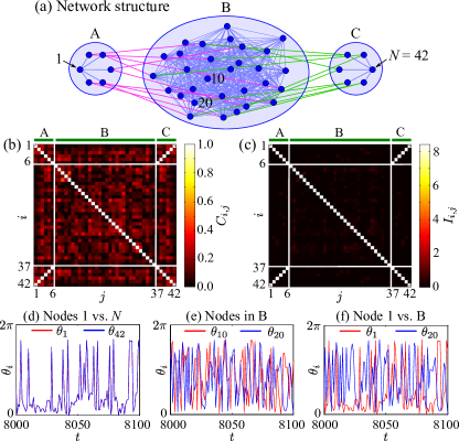
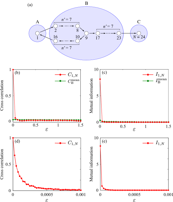
To systematically search for IMRS, we propose the following general recipe for designing a system: 1) construct a network structure that has a mirror symmetry and satisfies the size-one cluster requirement in B; 2) select chaotic node dynamics; 3) find system parameters for which the synchronization between nodes and is stable (i.e., ) and the dynamics of is chaotic (i.e., ); and 4) verify incoherence in B (i.e., small and ). As an example algorithm for generating networks for step above, we use the following procedure (for which we provide software; see Supplemental Material sm ). Given , , and () nodes in A, B, and C, respectively, we first connect each pair of nodes in B with probability . Next, we connect node to all the other nodes in A and node to all the other nodes in C. The nodes in A other than node are then paired up with the nodes in C other than node . Finally, for each of these node pairs, we choose nodes randomly from B and connect each of these nodes to the node pair. An example network constructed by this procedure is shown in Fig. 2(a). The probability of having a cluster of size in B can be kept small by making the size of B large enough. Here we generate networks with and use only those with no cluster of size in B.
As an example dynamics for the network leading to IMRS, we use coupled maps that model the electro-optic experimental system pecora1 , although we note that continuous-time systems also exhibit IMRS (see Supplemental Material sm , Sec. S1). The system dynamics is governed by
| (2) |
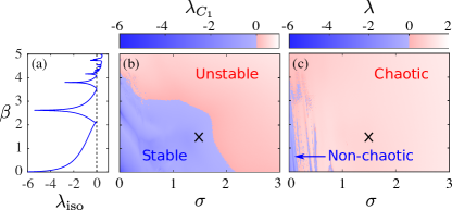
where is the phase shift in time step for the th component of the spatial light modulator array used in the experiment, is the strength of self-feedback coupling for the array components, and the offset is introduced to suppress the trivial solution, . We set for all computations for this system. The intensity of light is related to the phase shift through the nonlinear function . The dynamics of an isolated oscillator has a globally stable fixed point for small , which, through a sequence of period-doubling bifurcations, becomes chaotic for larger values of [see Fig. 3(a)].
As shown in Fig. 3(b), we find that networks generated by the procedure described above can achieve (i.e., stable synchronization between nodes and ) when and are both relatively small. These networks all have a mirror symmetry by construction, and they satisfy both conditions (i) and (ii). Figure 3(c) shows that, even when we start with oscillators that are not chaotic in isolation [, see Fig. 3(a)], the dynamics of the clusters becomes chaotic (i.e., ) as the coupling strength is increased. We thus see that there is a wide range of parameters and for which the network realizes stable chaotic synchronization. To check condition (iii), we compute and over time steps and time delay for and [black crosses in Figs. 3(b) and 3(c)]. The results, shown in Figs. 2(b) and 2(c), verify that condition (iii) is indeed satisfied. The corresponding system dynamics is illustrated by the time plots in Figs. 2(d)–(f). Thus, the network exhibits IMRS for these specific parameters. Moreover, Figs. 2(b) and 2(c) clearly show that the dynamics of the nodes in B is also incoherent relative to nodes and . While Eq. (2) is a discrete-time analog of Eq. (1), we expect IMRS to be observed for a range of different node dynamics, including both discrete-time and continuous-time dynamics, as well as for many mirror-symmetric network topologies not necessarily generated by the procedure described above.
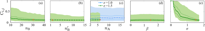
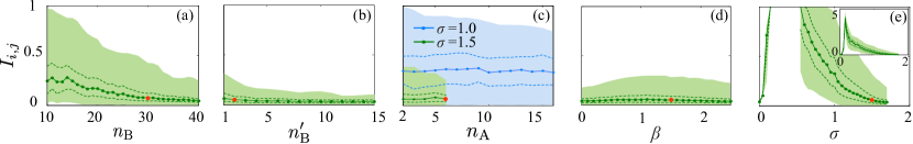
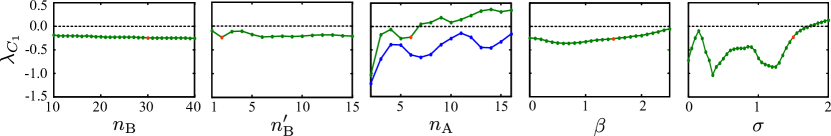
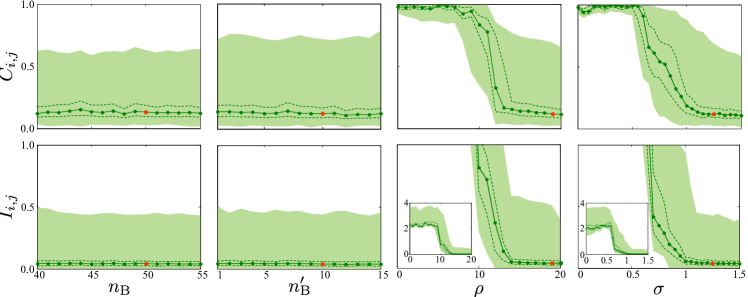
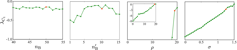
How does IMRS depend on system parameters? To answer this question, we study the distribution of (Fig. 4) and (Fig. S2 in Sec. S2 of Supplemental Material sm ) over all B as functions of parameters , , , , and . We verify for the entire range of parameter values over which the curves are drawn in Fig. 4 (see Supplemental Material sm , Sec. S2 for more details, including parameter dependence of ). As indicated by their th and th percentiles (dashed curves), the cross correlation and mutual information remain low for most node pairs in B for a range of system parameters, with the exception of cases with small . The medians of these coherence measures are mostly monotonically decreasing functions of up to the largest value of () for which [Fig. 4(e) and Fig. S2(e)]. We have at , indicating that all nodes in B are perfectly correlated in that case, simply because the isolated oscillators all converge to a common stable fixed point for . The median cross correlation and the median mutual information appear to be slightly decreasing functions of and , while they seem to be approximately constant as functions of (both for and ) and of . Note, however, that the synchronization stability does depend on : we observe that nodes and cannot synchronize stably for for [green curves ending at in Fig. 4(c) and Fig. S2(c)] but remain stably synchronized up to for [blue curves in Fig. 4(c) and Fig. S2(c)]. The loss of synchronization stability for sufficiently large is likely due to incoherent dynamics of the other nodes in groups A and C (see Supplemental Material sm , Sec. S3). Since these nodes are the only ones that directly influence the dynamics of nodes and (and thus their synchronization stability), the larger the number of these dynamically incoherent nodes (i.e., the larger ), the more difficult for nodes and to stably synchronize. Overall, we find that IMRS is observed for a wide range of structural and dynamical parameters of the system (see Supplemental Material sm , Sec. S4 for similar robustness observed for a continuous-time system).
We also find that the low levels of coherence between node (or ) and the nodes in B are maintained over a range of parameter values, following dependence patterns similar to those of the coherence levels within B (see Supplemental Material sm , Sec. S5). Low coherence between periphery and intermediate nodes has also been observed in certain cases of remote synchronization Sande2008 ; Soriano2012 [but with pairs of identically synchronized oscillators in the intermediate part of the network, which is not compatible with the IMRS condition (iii)].
A key aspect of IMRS lies in its behavior against noise. While the synchronization of nodes and is robust against independent noise added to the dynamics in A and C only up to a certain level (which is expected), IMRS is completely insensitive to noise in B, even when the noise level is very high (see Supplemental Material sm , Sec. S6). This characteristic robustness of IMRS stems from the mirror symmetry and is also associated with the dynamical incoherence in condition (iii). In contrast, (remote) synchronization of nodes and can be extremely sensitive to noise in B when some nodes in B are identically synchronized. This is demonstrated using the network topology considered in Ref. Sande2008 (see Supplemental Material sm , Sec. S7).
Our demonstration of IMRS challenges the notion that paths of communication between nodes that are exchanging information should be somehow observable. A particularly striking feature of IMRS we studied here is that the coupling between A and B, as well as B and C, is bidirectional. This allows information to be transferred from A to C through B, despite the scrambling of that information by the incoherent chaotic dynamics of B, which reduces the amount of shared information in B to a level that is too low for eavesdroppers (as measured by mutual information). This feature fundamentally sets IMRS apart from a master-slave type of chaos synchronization Pecora:1990 , in which the dynamics of B influences that of A and C, but not vice versa, thus prohibiting communication between nodes and . Similar master-slave synchronization can be observed even when B is replaced by noise, if the average of the noise is nonzero and its effect is equivalent to parameter change that drives the dynamics into synchrony Herzel:1995 .
A defining characteristic of IMRS we demonstrated is the dynamical incoherence within group B, which is allowed in the presence of the mirror symmetry we established as a general condition for observing IMRS. While we focused on undirected networks here, an analog of mirror symmetry can be formulated for directed networks using the notion of input equivalence Stewart:2003 . Since zero-lag synchronization of distant areas of the brain has been experimentally observed Roelfsema:1997 ; Rodriguez:1999 ; Soteropoulus:2006 , our results suggest the intriguing possibility that a mirror symmetry is hidden deep inside the synaptic connectivity structure. We hope that our discovery will spark the interest of many researchers and lead to further discoveries of fundamental connections between hidden network symmetry and emergent collective behavior in complex systems.
This work was supported by the NSFC (Award No. 61274042), CSC, 2013 Doctoral Innovation Funds of SWJTU, and ARO (Award No. W911NF-15-1-0272). The authors thank Prof. Wei Pan for comments on the manuscript.
References
- (1) A. Pikovsky, M. Rosenblum, and J. Kurths, Synchronization: A Universal Concept in Nonlinear Sciences (Cambridge University Press, Cambridge, England, 2003).
- (2) L. M. Pecora and T. L. Carroll, Master stability functions for synchronized coupled systems, Phys. Rev. Lett. 80, 2109 (1998).
- (3) K. Kaneko, Clustering, coding, switching, hierarchical ordering, and control in a network of chaotic elements, Physica D 41, 137 (1990).
- (4) I. Stewart, M. Golubitsky, and M. Pivato, Symmetry groupoids and patterns of synchrony in coupled cell networks, SIAM. J. Appl. Dyn. Syst. 2, 609 (2003).
- (5) F. Sorrentino and E. Ott, Network synchronization of groups, Phys. Rev. E 76, 056114 (2007).
- (6) T. Dahms, J. Lehnert, and E. Schöll, Cluster and group synchronization in delay-coupled networks, Phys. Rev. E 86, 016202 (2012).
- (7) L. M. Pecora, F. Sorrentino, A. M. Hagerstrom, T. E. Murphy, and R. Roy, Cluster synchronization and isolated desynchronization in complex networks with symmetries, Nat. Commun. 5, 4079 (2014).
- (8) H. G. Winful and L. Rahman, Synchronized chaos and spatiotemporal chaos in arrays of coupled lasers, Phys. Rev. Lett. 65, 1575 (1990).
- (9) I. Fischer, R. Vicente, J. M. Buldú, M. Peil, C. R. Mirasso, M. C. Torrent, and J. García-Ojalvo, Zero-lag long-range synchronization via dynamical relaying, Phys. Rev. Lett. 97, 123902 (2006).
- (10) G. Van der Sande, M. C. Soriano, I. Fischer, and C. R. Mirasso, Dynamics, correlation scaling, and synchronization behavior in rings of delay-coupled oscillators, Phys. Rev. E 77, 055202 (2008).
- (11) M. C. Soriano, G. Van der Sande, I. Fischer, and C. R. Mirasso, Synchronization in simple network motifs with negligible correlation and mutual information measures, Phys. Rev. Lett. 108, 134101 (2012).
- (12) A. Bergner, M. Frasca, G. Sciuto, A. Buscarino, E. J. Ngamga, L. Fortuna, and J. Kurths, Remote synchronization in star networks, Phys. Rev. E 85, 026208 (2012).
- (13) A. Viriyopase, I. Bojak, M. Zeitler, and S. Gielen, When long-range zero-lag synchronization is feasible in cortical networks, Front. Comput. Neurosci. 6, 49 (2012).
- (14) V. Nicosia, M. Valencia, M. Chavez, A. Díaz-Guilera, and V. Latora, Remote synchronization reveals network symmetries and functional modules, Phys. Rev. Lett. 110, 174102 (2013).
- (15) L. V. Gambuzza, A. Cardillo, A. Fiasconaro, L. Fortuna, J. Gómez-Gardeñes, and M. Frasca, Analysis of remote synchronization in complex networks, Chaos 23, 043103 (2013).
- (16) Y. Kuramoto and D. Battogtokh, Coexistence of coherence and incoherence in nonlocally coupled phase oscillators, Nonlinear Phenom. Complex Syst. 5, 380 (2002).
- (17) D. M. Abrams and S. H. Strogatz, Chimera states for coupled oscillators, Phys. Rev. Lett. 93, 174102 (2004).
- (18) A. M. Hagerstrom, T. E. Murphy, R. Roy, P. Hövel, I. Omelchenko, and E. Schöll, Experimental observation of chimeras in coupled-map lattices, Nat. Phys. 8, 658 (2012).
- (19) M. R. Tinsley, S. Nkomo, and K. Showalter, Chimera and phase-cluster states in populations of coupled chemical oscillators, Nat. Phys. 8, 662 (2012).
- (20) M. J. Panaggio and D. M. Abrams, Chimera states: coexistence of coherence and incoherence in networks of coupled oscillators, Nonlinearity 28, R67 (2015).
- (21) K. M. Cuomo, A. V. Oppenheim, and S. H. Strogatz, Synchronization of Lorenz-based chaotic circuits with applications to communications, IEEE Trans. Circuits Syst. II 40, 626 (1993).
- (22) A. Argyris et al., Chaos-based communications at high bit rates using commercial fibre-optic links, Nature 438, 343 (2005).
- (23) H. Koizumi et al., Information-theoretic secure key distribution based on common random-signal induced synchronization in unidirectionally-coupled cascades of semiconductor lasers, Opt. Exp. 21, 17869 (2013).
- (24) L. Zhang et al., Conceal time-delay signature of mutually coupled vertical-cavity surface-emitting lasers by variable polarization optical injection, IEEE Photon. Technol. Lett. 24, 1693 (2012).
- (25) T. M. Cover and J. A. Thomas, Elements of Information Theory (John Wiley Sons, 1991).
- (26) See Supplemental Material for results on networks of coupled Lorenz oscillators and other supporting details. Supplemental Material also includes the MATLAB code for generating the random mirror-symmetric networks used in our study.
- (27) L. M. Pecora and T. L. Carroll, Synchronization in chaotic systems, Phys. Rev. Lett. 64, 821 (1990).
- (28) H. Herzel and J. Freund, Chaos, noise, and synchronization reconsidered, Phys. Rev. E 52, 3238 (1995).
- (29) P. R. Roelfsema, A. K. Engel, P. König, and W. Singer, Visuomotor integration is associated with zero time lag synchronization among cortical areas, Nature 385, 157 (1997).
- (30) E. Rodriguez et al., Perception’s shadow: long-distance synchronization of human brain activity, Nature 397, 430 (1999).
- (31) D. S. Soteropoulus and S. N. Baker, Cortico-cerebellar coherence during a precision grip task in the monkey, J. Neurophysiol. 95, 1194 (2006).
Supplemental Material
Incoherence-Mediated Remote Synchronization
Liyue Zhang, Adilson E. Motter, and Takashi Nishikawa
S1 Networks of coupled Lorenz oscillators
As an example of continuous-time systems exhibiting IMRS, we consider a network of coupled Lorenz oscillators, whose dynamics is governed by
| (S1) |
which has the same form as Eq. (1) of the main text. Figure S1 shows results analogous to Fig. 2 of the main text for this system. We use network topologies constructed by our procedure with , , , and (and thus ). Figure S1 confirms that, for , , , and , we indeed observe IMRS.
S2 Dependence of IMRS on system parameters
To complement the results in Fig. 4 for the system in Eq. (2), we also compute the mutual information and the Lyapunov exponent for the synchronization of cluster as a function of the parameters , , , , and . The results are shown in Figs. S2 and S3, respectively. As in Fig. 4, in each plot the parameters are set to the values used in Fig. 2 (indicated by red dots), except for the one being varied. Both quantities are averaged over ten network realizations and ten initial conditions.
S3 Dynamics of nodes in groups A and C
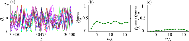
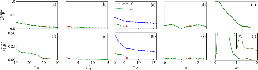
Since each node in group A is identically synchronized with the corresponding node in group C in a system exhibiting IMRS, we only need to consider the dynamics in A. Figure S4 shows low cross correlation and mutual information observed between the (chaotic) dynamics of the nodes within A (other than node ) for the system in Eq. (2). Here we use and to denote the mean value of the correlation and mutual information , respectively, over all node pairs , , . We normalize by the mean value of the entropy of the time series among the nodes in group A other than node . We find that the level of coherence is approximately constant as a function of , the number of nodes in A.
S4 Robustness against parameter changes for Lorenz oscillator networks
Here we study the robustness of IMRS for the networks of coupled Lorenz oscillators. Figure S5 is an analog of Fig. 4 and Fig. S2, which shows that the cross correlation and mutual information remain low for a range of parameters , , , and . Similarly, Fig. S6 is an analog of Fig. S3, which shows the parameter dependence of the synchronization stability between nodes and . Note that, for this system, the synchronization is unstable for .
S5 Coherence between node and group B vs. system parameters
Here we measure the coherence between node and group B by
| (S2) |
which are plotted for the system in Eq. (2) as functions of parameters , , , , and in Fig. S7. We see that the behavior of these functions is very similar to Fig. 4 and Fig. S2.
S6 Robustness against noise
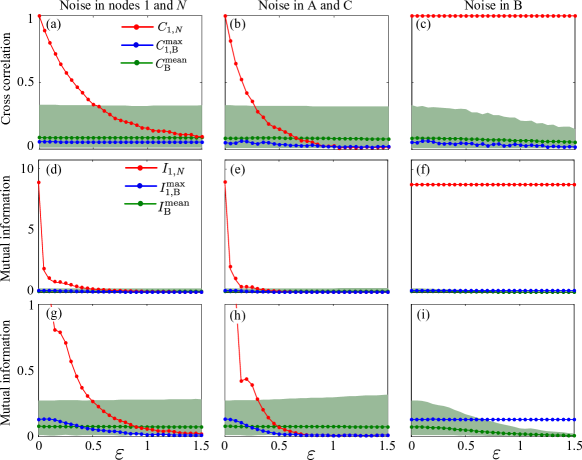
To test the robustness of IMRS against dynamical noise, we add independent Gaussian noise with mean zero and variance to the phase variable of nodes in different parts of the network described by Eq. (2). We use the parameter values from Fig. 2. Regardless of where the noise is added, the coherence among the nodes in B, as well as between node and the nodes in B, remains low (and approximately constant) as a function of . This can be seen in Fig. S8, where we plot the quantities
| (S3) |
as well as and defined in Eq. (S2). The level of synchronization between nodes and decreases as increases (as expected) if the noise is added to nodes and themselves or to the other nodes in A and C (see and in the first and second columns of Fig. S8). In contrast, we observe that synchronization is not affected at all by the noise if it is added to B, even for very large , despite the fact that nodes and are interacting with the nodes in B through network paths connecting them (see and , the red curves in the third column of Fig. S8).
S7 Consequence of having synchronized oscillators in B
To demonstrate that remote synchronization can be sensitive to noise in B when some nodes in B are identically synchronized, we consider the (directed) network topology used in the example system of Ref. Sande2008 . This topology is illustrated in Fig. S9(a). Using for the topology (making it a network of nodes), for the node dynamics in Eq. (2), and for the coupling strength in Eq. (2), the system exhibits stable synchronization between nodes and [and thus for , as shown in Fig. S9(b)], while most node pairs within B show incoherent dynamics [low and in Figs. S9(b) and S9(c), respectively, where and are both defined in Eq. (S3)]. However, there are pairs of nodes in B that are identically synchronized in this system Sande2008 : nodes and , nodes and as well as nodes and . The synchronization of these pairs are sensitive to independent noise [for the same reason we observe sensitivity in the red curves in Figs. S8(b), S8(e), and S8(h)], which leads to the sensitivity of the synchronization between nodes and . This is demonstrated by the sharp drop of the red curves in Figs. S9(b)–S9(e) as is increased from zero, where the phase variable of each node in B is subject to independent additive Gaussian noise with mean zero and variance . We observe that the sensitivity of the synchronization between nodes and is even more drastic than in Figs. S8(b), S8(e), and S8(h). We argue that this is due to the amplification of the effect of noise along the path from node to node or . When noise is added to a node in B, the resulting deviation of the node’s state propagates to other nodes and is amplified along the path from that node to node or . Thus, the synchronization between nodes and is more sensitive to noise added to B than to noise added to nodes and .
MATLAB code for generating the random mirror-symmetric networks used in our study (file name: mirror_sym_net.m):
function net = mirror_sym_net(nA,nB,nBp,p)
% Generates a random mirror-symmetric network following the procedure
% described in the paper.
%
% Output: struct variable ’net’ with fields, ’nA’, ’nB’, ’nBp’, ’p’, ’A’
%
% If no input argument is given, it will use:
%
%   nA = 6, nB = 30, nBp = 2, p = 0.8
%
% The indexing for the adjacency matrix ’net.A’ is as follows:
%
%   Group A: i = 1, ... ,nA
%   Group B: i = nA+1, ..., nA+nB
%   Group C: i = nA+nB+1, ..., N (= 2*nA + nB)
%
% Copyright (c) 2017 by Takashi Nishikawa

if nargin == 0
    nA = 6; nB = 30; nBp = 2; p = 0.8;
end
% nL = nA-1;

N = 2*nA + nB;
A = zeros(N);

% Connect nodes in group B.
for i = nA+1:nA+nB
    for j = i+1:nA+nB
        if rand <= p; A(i,j) = 1; A(j,i) = 1; end
    end
end

% Connect Node 1 and N to other nodes in groups A and C, respectively. Also
% connect nodes in groups A and C to nodes in group B.
for i = 2:nA
    A(1,i) = 1; A(i,1) = 1;
    A(N, N-i+1) = 1; A(N-i+1, N) = 1;
    nrm=randperm(nB);
    ix = nA + nrm(1:nBp);
    A(ix,i) = 1; A(i,ix) = 1;
    A(ix, N-i+1) = 1; A(N-i+1, ix) = 1;
end

net = struct(’nA’, nA, ’nB’, nB, ’nBp’, nBp, ’p’, p, ’A’, A);