Transport signatures of top-gate bound states with strong Rashba-Zeeman effect
Abstract
We suggest a single-mode spin injection scheme in non-ferromagnetic quantum channels utilizing perpendicular strong Rashba spin-orbit and Zeeman fields. By applying a positive top-gate potential in order to inject electrons from the spin-orbit gap to the low-energy regime, we observe coherent destruction of transport signatures of a hole-like quasi-bound state, an electron-like quasi-bound state, or a hole-like bound state features that are sensitive to the selection of the top-gate length along the transport direction.
pacs:
73.23.-b, 72.25.Dc, 72.30.+qIntroduction.
Quasi-one-dimensional narrow constrictions in two-dimensional electron gases (2DEGs) are among the most widely studied elements illustrating the wave and spin nature of electrons for both application and fundamental arenas for many years Wharam1988 ; vanWees1988 ; Thomas1996 ; Bardarson04 . Spintronics utilizing the spin degree of freedom of conduction electrons is one of the most promising paradigms for the development of novel devices for applications from logic to storage devices with low power consumption. For the purposes of spintronics applications, narrow band gap semiconducting materials being integrated for verification of spin transport would be of great interest Datta90 ; Governale02 ; Aharony2008 . This could be achieved either through detection of the spin current or spin accumulation at the edges of the device. Generation, detection, and manipulation of electron spin in mesoscopic systems has thus been the aim of spintronics for both application and fundamental arenas Wolf2001 ; Aws2002 ; Malshukov03 ; Zutic2004 ; Malshukov05 .
For a built-in electric field perpendicular to the asymmetric 2DEG plane, the momentum-dependent spin-orbit magnetic field is aligned perpendicular to the quantum channel and in the plane of 2DEG (Rashba effect) Rashba60 ; Bychkov1986 ; Galitski13 . The spin-orbit interaction (SOI) has attracted much attention on account of its possible applications in spin-based electronics since the Datta-Das spin transistor was proposed Datta90 . The essential requirement for spintronic devices is to manipulate the free electron spins that can be achieved via an external active control. Since Nitta et al. Nitta1997 showed that the Rashba SOI can be controlled, interest in utilizing the Rashba SOI to manipulate electron spins in constricted systems has been growing. The control of Rashba interaction was demonstrated to be material and structure sensitive Eldridge2008 ; Sheremet2016 . The combination of strong Rashba and weak Zeeman fields would induce a spin-orbit gap Pershin2004 ; Quay2010 ; Sadreev2013 ; Loss2014 or a helical gap Cayao15 . Very recent experimental and theoretical studies Manchon15 ; Kammermeier16 ; Heedt17 have successfully shown that the presence of strong Rashba coupling in InAs nanowires can be used for spin manipulation. In our previous works Tang2012 ; Tang2015 ; Tang2017 , we have considered delta profile finger-gate controlled spin-polarized transport and thus did not need to consider evanescent and propagating modes in the gate region.
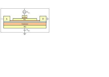
In this Letter we consider a top-gate controlled quantum device (see Fig. 1) under an in-plane oriented magnetic field parallel to the direction of current flow. A back-gate voltage is applied for tuning the Fermi energy of conduction electrons in the anisotropic 2DEG between the split-gates and the back-gate. A similar experimental set-up has been proposed Kammermeier16 , in which the top-gate acts upon a hexagonal cross-section wire forming a quantum point contact.
We shall show that around the spin subband minima or maxima, Fabry-Pérot interferences between propagating modes would be suppressed, and new transmission resonances with different properties occur due to the coupling to spin-resolved evanescent modes. The application of voltage at the top-gate results in potential barrier in the channel and determines the shift of energy dispersion in the gate region. As a result, within a single-mode spin injection scheme, we observe that the spin-polarized dc conductance spectra may reveal significant electron-like and hole-like quasi-bound states (QBSs) as well as hole-like bound states (BSs) features depending on the selection of the length and the applied voltage of the top-gate.
Spin dependent transport.
We consider a Rashba quantum channel in the plane of the 2DEG confinement to be located at = , and a magnetic field contributes the Hamiltonian via the spin Zeeman term . In the absence of a top-gate, the system can be described by an unperturbed Hamiltonian
| (1) |
The first two terms describe an ideal quantum channel Tang2012 ; Tang2015 ; Tang2017 . In addition, the third term is the Rashba effect induced by a built-in electric field due to asymmetric 2DEG confinement, and the last term denotes the Zeeman effect induced by an in-plane magnetic field. Below, we employ the Fermi level as an energy unit = and the inverse wave number as a length unit . Correspondingly, we define the Rashba coefficient unit and magnetic field unit = for convenience. The Rashba interaction can be expressed as in a narrow constriction Tang2012 . The Zeeman term = is characterized by the half-Landé factor = .
In this work we show how the spin-polarized electron transport in a quantum channel is influenced by a dc top-gate (see Fig. 1). The top-gate electric potential energy is modeled by a rectangular form = for simplicity where = and is the Heaviside step function. Plane wave solution for the eigenvalues of the Schrödinger equation gives the spin dependent energy dispersion of the top-gate device
| (2) |
with = denoting the spin-up () and spin-down () branches, and eigenvectors
| (3) |
with = .
In the absence of a magnetic field, the two lateral spin-split subbands are lowered by a spin-orbit energy and shifted in momentum-space by the spin-orbit wave number = ( = 0 T) Heedt17 . For a given subband , the spin-orbit energy = can be defined by the energy difference between the degenerate energy crossing point = at wave number = and the subband bottom of the lower spin branch = .
In the presence of a magnetic field, the two vertical spin-split subbands are lowered by a -dependent spin-orbit energy and shifted in momentum-space by the magneto-spin-orbit wave number
| (4) |
In the presence of the Zeeman term, the spin-orbit energy is modified and can be defined by the energy difference between the lower spin branch top = at wave number and the lower spin branch bottom = . This gives a magneto-spin-orbit energy
| (5) |
in which both a linear and a quadratic term of the Zeeman factor appear.
We would like to bring reader’s attention to the Eq. (2) that only shows the energy dispersions of the propagating modes. In order to calculate both the propagating and evanescent modes associated with the multiple scattering by the dc-biased top-gate, one has to consider the incident electron with a given energy = in the subband by solving the quantum dynamic equation Tang2015 .
| (6) |
Solving this equation for a given energy allows us to determine all wave numbers , real or complex, corresponding to propagating or evanescent modes, respectively.
In the quantum channel the top-gate boundaries couple spin-split propagating modes to spin-flip non-propagating modes. Therefore, the transport current causes localized modes to build up around the top-gate edges. A top-gate propagation matrix method is used to take four spin-split right-moving and left-moving states into account, given by
| (7) |
Here two step propagation matrices (step-up and step-down) as well as two free propagation matrices (with and without ) are involved to incorporate multiple scattering at the two ends of the top-gate. The transmission and reflection matrices are, respectively, = and = involving spin-preserve and spin-flip contributions. Taking the derivative of Eq. (2), one obtains the group velocity of the spin mode that allows us to determine a local minimum or a maximum in the energy spectrum Tang2012 ; Tang2015 ; Tang2017 . Solving for the spin flip and non-flip coefficients, one uses the Landauer-Büttiker formula to obtain the spin-polarized conductance Landauer1970 ; Buttiker1990
| (8) |
Here is the conductance quantum per spin state of an electron, is the number of an occupied subband, and indicates the transmission amplitude of the th subband electron incident from the spin state scattered to the spin state. Zero temperature is assumed.
Results and discussion.
In our previous works we have presented that the finger-gate in a quantum channel, with strong SOI in the presence of a longitudinal in-plane magnetic field, results in bound state features in the conductance Tang2012 ; Tang2015 ; Tang2017 . However, these studies assumed that the finger gates have a delta profile and hence a mixture of evanescent and propagating modes is not present. Below we shall show our numerical calculations for the investigation of top-gate bound state features for a finite gate length .
Calculations presented below are carried out under the assumption of a 2DEG at a high-mobility InAs-In1-xGaxAs interface with effective electron mass = , effective Landé factor = , and typical electron density cm-2 Nitta1997 . Accordingly, the energy unit = = 66 meV, the length unit = = 5.0 nm, the magnetic field unit = kT, and the Rashba coefficient is in units of = 330 meV nm Tang2012 . We consider channel width = = nm that carries a single propagating mode with an ideal subband bottom energy = . Below we deal with interference of the spin-polarized electron waves between the channel and the top-gate with negligible inter-subband transitions based on an assumption of giant subband spacing.
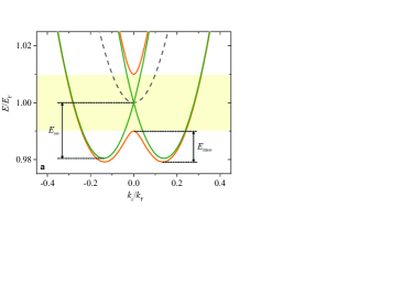
In Fig. 2(a) we present the lowest subband energy dispersion obtained from Eq. (2) for = = 0 (dash); = 0.14 at = 0 (green); and = 0.14 at = 0.01 (orange) with = T. In the absence of a magnetic field, the spin-orbit energy = corresponds to spin-orbit wave numbers = . The parameters satisfying the strong SOI criterion results in a spin-orbit gap = as shown by the shaded area.
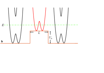
Figure 2(b) shows the schematic of our suggested single-mode spin injection scheme. This can be achieved using an appropriate positive top-gate potential energy and the Rashba coefficient . The top-gate shifted lower spin branch in the energy interval with magneto-spin-orbit energy is then located within the spin-orbit gap energy interval in the leads. We shall show that various BS or QBS features can be observed depending on the application of the top-gate length in this spin injection regime.
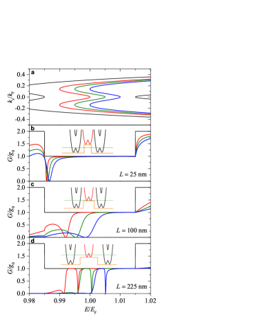
For illustration Fig. 3 shows (a) the lowest subband energy dispersion and (b)-(d) conductance spectra of various top-gate potential energies = 0.015 (red), 0.020 (green), and 0.025 (blue) for the Rashba coefficient = at = . Here the magneto-spin-orbit energy = 0.01 and the spin-orbit gap energy = 0.03 in order to inject electrons from the spin-orbit gap to the low-energy regime, satisfying the criterion where the strength of top-gate potential is between the magneto-spin-orbit energy and the spin-orbit gap.
For the application of top-gate with short length, the electron modes occupying the subbands in the leads dominate the transport properties. For applying a positive top-gate potential energy, the conductance spectrum thus reveals a hole-like QBS feature located around the lower spin branch top = 0.985 in the leads, as depicted in Fig. 3(b) and in the inset. This QBS feature can also be found finger-gate systems Tang2012 or refers to the Fano-Rashba resonances David06 ; David08 . Our results imply that the finger-gate model is valid if the length of the top-gate is shorter than the Fermi wave number.
For an intermediate top-gate length ( = 100 nm), the hole-like QBS feature shown in Fig. 3(b) is suppressed and reduces to a knickpoint. Instead, the electron occupying the outer propagating mode in the spin-orbit gap in the leads may be scattered into the lower spin branch bottoms in the top-gate (see Fig. 3(c), inset). As a result, the electron is allowed to make spin-flip transitions forming an electron-like QBS in the top-gate around the energy
| (9) |
that is related to the Zeeman factor and shifted by the top-gate potential energy . This transport signature exhibits the coupling of an outer propagating mode in the leads and evanescent modes around the bottoms of the shifted lower spin branch in the top-gate. The conductance valley broadens with increasing . Suppose the length of the top-gate is between short and intermediate situations, such as = 60 nm (not shown), the conductance drops become broader and locate between the lead band top and the top-gate band bottom of the lower spin branch.
Now we turn to consider the top-gate with a sufficient long length ( = 225 nm) as shown in Fig. 3(d). We see that the electron-like QBS feature shown in Fig. 3(c) is strongly suppressed. A sufficient long significantly enhances the electron dwell time in the top-gate region and favors multiple scattering. As a result, a hole-like BS feature can be observed if the electron is injected into the top-gate region with energy at the reverse point of the inner mode in the top-gate shifted lower spin branch. Figure 3(d) shows clear sharp dip structures in the conductance spectra with conductance zeros. Here the electrons, occupying the inner modes below the shifted subband top energies = + , behave a hole-like BS feature at = 0.996, 1.001, and 1.005 for = 0.015, 0.020, and 0.025, respectively. These hole-like BS energies are at the reverse point energies
| (10) |
of the inner modes in the top-gate shifted lower spin branch, as depicted in the inset. Here the inverse of the second derivative of the energy dispersion is divergent leading to a divergent effective mass.
Concluding remarks.
We have considered a top-gate controlled quantum device with spin-orbit coupling and an external in-plane magnetic field. Since the effective spin-orbit field and Zeeman field are perpendicular, the spin-orbit gap can be induced in the strong spin-orbit coupling regime. Transport signatures have been demonstrated for electrons incident from spin-orbit gap energies though a top-gate with positive electric potential energies. Our theoretical calculations suggest possible conditions and mechanisms of an electron-like QBS, a hole-like QBS, or a hole-like BS feature in continuum. Our calculations can be used to extract information of spin-orbit gap involved top-gate tunneling spectroscopy experiments, such as the recently reported measurements in Heedt et al. Heedt17 .
Acknowledgements.
The authors acknowledge financial supports from Ministry of Science and Technology in Taiwan under grant No. 106-2112-M-239-001-MY3, the Research Fund of the University of Iceland, the Icelandic Research Fund under grant No. 163082-051, and the Icelandic Instruments Fund.References
- (1) D. A. Wharam, T. J. Thornton, R. Newbury, M. Pepper, H. Ahmed, J. E. F. Frost, D. G. Hasko, D. C. Peacock, D. A. Ritchie, G. A. C. Jones, J. Phys. C: Solid State Phys. 21, (1988) L209.
- (2) B. J. van Wees, H. van Houten, C. W. J. Beenakker, J. G. Williamson, ; L. P. Kouwenhoven, D. van der Marel, C. T. Foxon, Phys. Rev. Lett. 60, (1988) 848-850.
- (3) K. J. Thomas, J. T. Nicholls, M. Y. Simmons, M. Pepper, D. R. Mace, and D. A. Ritchie, Phys. Rev. Lett. 77, (1996) 135.
- (4) J. H. Bardarson, I. Magnusdottir, G. Gudmundsdottir, C.-S. Tang, A. Manolescu, and V. Gudmundsson Phys. Rev. B 70, (2004) 245308.
- (5) S. Datta and B. Das, Appl. Phys. Lett. 56, (1990) 665.
- (6) M. Governale, D. Boese, U. Z Lulicke, and C. Schroll, Phys. Rev. B 65, (2002) 140403.
- (7) A. Aharony, O. Entin-Wohlman, Y. Tokura, and S. Katsumoto, Phys. Rev. B 78, (2008) 125328.
- (8) S. A. Wolf, D. D. Awschalom, R. A. Buhrman, J. M. Daughton, S. von Molnr, M. L. Roukes, A. Y. Chtchelkanova, and D. M. Treger, Science 294, (2001) 1488.
- (9) D. D. Awschalom, D. Loss, and N. Samarth, Semiconductor Sprintronics and Quantum Computation (Springer, Berlin, 2002).
- (10) A. G. Mal’shukov, C. S. Tang, C. S. Chu, and K. A. Chao, Phys. Rev. B 68, (2003) 233307.
- (11) I.utić, J. Fabian, and S. Das Sarma, Spintronics: Fundamentals and applications, Rev. Mod. Phys. 76, (2004) 323.
- (12) A. G. Mal’shukov, C. S. Tang, C. S. Chu, and K. A. Chao, Phys. Rev. Lett. 95, (2005) 107203.
- (13) E. I. Rashba, Sov. Phys. Solid State 2, (1960) 1109.
- (14) Y. A. Bychkov and E. I. Rashba, J. Phys. C 17, (1984) 6039.
- (15) V. Galitski and I. B. Spielman, Nature 494, (2013) 7435.
- (16) J. Nitta, T. Akazaki, H. Takayanagi, and T. Enoki, Phys. Rev. Lett. 78, (1997) 1335.
- (17) P. S. Eldridge, W. J. H. Leyland, P. G. Lagoudakis, O. Z. Karimov, M. Henini, D. Taylor, R. T. Phillips, and R. T. Harley, Phys. Rev. B 77, (2008) 125344.
- (18) A. S. Sheremet, O. V. Kibis, A. V. Kavokin, and I. A. Shelykh, Phys. Rev. B 93, (2016) 165307.
- (19) Y. V. Pershin, J. A. Nesteroff, and V. Privman, Phys. Rev. B 69, (2004) 121306(R).
- (20) C. H. L. Quay, T. L. Hughes, J. A. Sulpizio, L. N. Pfeiffer, K.W. Baldwin, K.W.West, D. Goldhaber-Gordon, and R. de Picciotto, Nat. Phys. 6, (2010) 336.
- (21) A. F. Sadreev and E. Ya. Sherman, Phys. Rev. B 88, (2013) 115302.
- (22) D. Rainis and D. Loss, Phys. Rev. B 90, (2014) 235415.
- (23) J. Cayao, E. Prada, P. San-Jose, and R. Aguado, Phys. Rev. B 91, (2015) 024514.
- (24) A. Manchon, H. C. Koo, J. Nitta, S. M. Frolov, and R. A. Duine, Nat. Materials 14, (2015) 871.
- (25) M. Kammermeier, P. Wenk, J. Schliemann, S. Heedt, and T. Schäpers Phys. Rev. B 93, (2016) 205306.
- (26) S. Heedt, N. Traverso Ziani, F. Crépin, W. Prost, S. Trellenkamp, J. Schubert, D. Grützmacher, B. Trauzettel, and T. Schapers, Nat. Phys. 13, (2017) 563.
- (27) C.-S. Tang, S. Y. Chang, and S. J. Cheng, Phys. Rev. B 86, (2012) 125321.
- (28) C.-S. Tang, S.-T. Tseng, V. Gudmundsson, and S.-J. Cheng, J. Phys.: Cond. Mat. 27, (2015) 085801.
- (29) C.-S. Tang, J.-A. Keng, N. R. Abdullah, and V. Gudmundsson, Phys. Lett. A, 381, (2017) 1529.
- (30) R. Landauer, Philos. Mag. 21, (1970) 863.
- (31) M. Büttiker, Phys. Rev. B 41, (1990) 7906.
- (32) D. Sánchez and L. Serra, Phys. Rev. B 74, (2006) 153313.
- (33) D. Sánchez and L. Serra, and M.-S. Choi, Phys. Rev. B 77, (2008) 035315.