Beyond Kerker’s conditions: simultaneously nearly zero forward and nearly zero backward scatterings
Abstract
With theoretical analyses and numerical calculations, we show that a passive scatterer at the sub-wavelength scale can simultaneously exhibit both nearly zero forward scattering (NZFS) and nearly zero backward scattering (NZBF). It is related to the interference of dipolar quadrupole modes of different origin, leading to coexistence of Kerker’s first and second conditions at the same time. For optical frequencies, we propose two different sets of composited materials in multi-layered nano-structures, i.e., and , for the experimental realization.
Scattering fields generated from a localized and finite-sized passive object can be well described by the multipole decomposition jackson ; multipole . A deep understanding on the constitutions of these multipole moments provides the ability to tailor and control the scattered field. In particular, through the interference between electric and magnetic dipoles, Kerker et al. kerker revealed the possibility to have an asymmetric field radiation with zero backward scattering (ZBS) or zero forward scattering (ZFS), which are known as the first and second Kerker’s conditions, respectively. Even though the power conservation and optical theorem limit the realization of perfect Kerker’s conditions opticaltheorem1 ; opticaltheorem2 ; kerker1 , these directional scattering patterns have been applied to unidirectional emission control antenna1 , as well as metasurfaces brewster ; huygen and metadevices antenna2 ; antenna3 , with recent experimental observations in nano-particles with high refractive index nanoparticle1 ; nanoparticle2 ; nanoparticle3 and magnetic spherical particles magnetic1 .
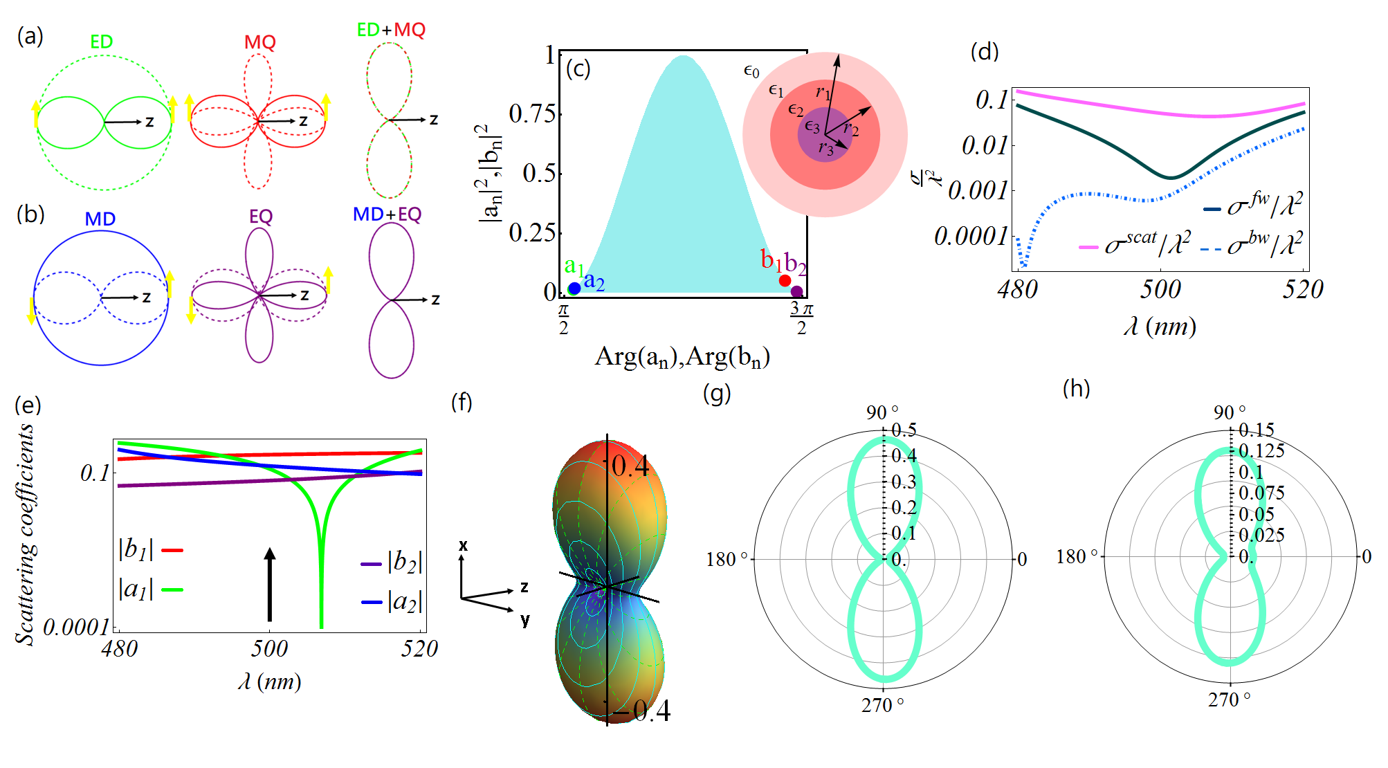
Nevertheless, both Kerker’s conditions are realized separately. In this Letter, we show that with higher order modes (i.e. quadrupoles), one can achieve these two conditions simultaneously, resulting in a passive scatterer exhibiting both NZFS and NZBS. To go beyond Kerker’s conditions, we need to have superposition of a dipole and quadrupole of different origin with a ratio in the modulus, as well as a phase difference . This result can be envisioned from the parity symmetry of corresponding modes, as shown in Figs. 1 (a)-(b). We will discuss them in detail later. Through the phase diagram kerker1 ; phase1 , two different sets of composited materials in a three-layered nano-sphere, i.e., and (from outer to inner regions), are found for the implementation in optical frequencies. The results revealed here can be readily served as a building block for directional emission controller, nano-antenna and metasurfaces.
Without loss of generality, we consider a spherical object, i.e., the scatterer, under an electromagnetic plane wave illumination, which has the form with the polarization of electric field in -direction. Here is the environmental wavenumber and denotes the angular frequency of this plane wave. Through spherical multipole decomposition, all fields can be constructed by proper choices of wave basis and coefficients book ; phase1 . Under the excitation of an incident field, power assignments in a passive system would be allocated for the radiative loss (scattering cross section, ) and the material dissipation loss (absorption cross section, ), along with the sum of them being the extinction cross section, i.e., . Even unexpected scattering phenomena can be found by embedding specific electromagnetic materials, power conservation law still exists intrinsically. In the representation of phasor for the scattering coefficient, we have , with denoting the partial absorption cross section. Consequence of this inequality results in a phase diagram shown in Fig. 1 (c), revealing all unexpected and interesting scattering results phase1 .
On the other hand, extinction cross section is also related to the forward scattering amplitude , i.e., . This is a manifestation of the optical theorem optical ; kerker1 . The scattering field in far-field regime then can be approximated as , with being the incident wave amplitude. It means that the radiative loss and material dissipation loss both contribute to the forward scattering amplitude. Due to positivity of and , thus, a zero value in the forward scattering amplitude imposes zeros both in the absorption and scattering cross sections. Correspondingly, forming zero forward scattering is impossible for passive systems. In addition, within a constant value of extinction cross section, the passive system can display same scattering amplitude in the forward direction, but with totally different absorption cross section involved kerker1 .
To tailor the far-field scattering distribution, the corresponding differential scattering cross section can be written as book ; opticaltheorem1 ; non-rayleigh :
| (1) |
Here, and are polarized scattering waves parallel and perpendicular to the scattering plane, respectively. Explicitly, the two polarized scattering waves have the form:
| (2) |
with the associated Legendre polynomial . The complex scattering coefficients for TM and TE modes are denoted as and , respectively.
To go beyond conventional Kerker’s conditions, we are looking for zero scattering in a desired direction by requiring and . Owing to the rotation symmetry in our scattering system, along with a plane wave excitation, here we only have a dependence on the azimuthal angle . Assume the dominant excitations are the lowest four multipole moments, i.e., (electric dipole), (magnetic dipole), (electric quadrupole), and (magnetic quadrupole). Then, to eliminate the scattering wave in a desired direction , the required conditions become:
| (3) | |||
| (4) |
If only dipole terms are involved, , to support denoted as ZFS or denoted as ZBS, we find or , respectively. For a homogeneous sphere, the conditions or , lead to the famous formula or for ZFS or ZBS, respectively kerker . Nevertheless, as indicated in phase diagram, see Fig. 1(c), it is impossible to meet a out-of-phase ( phase) condition due to the intrinsic constrain on the power conservation. Moreover, it is obvious that only with electric and magnetic dipoles, one can not satisfy Eqs. (3) and (4) at the same time.
Now, by considering the electric and magnetic quadrupoles, from Eqs. (3-4) the conditions to simultaneously suppress scattering field in the forward () and backward () directions can be found as:
| (5) |
This simple result reveals that even for the complicated interferences among four multipole moments, to achieve ZFS and ZBS simultaneously, a required phase difference is asked for the corresponding electric dipole (magnetic dipole) to the magnetic quadrupole (electric quadrupole), along with a ratio of modulus by .
To indicate physics behind our finding in Eq.(5), we employ the phase analysis of multipole moments with highlighting the parity in forward and backward directions liu . For the first (second) case of Eq.(5), i.e., with electric dipole (magnetic dipole) and magnetic quadrupole (electric quadrupole), in Figs. 1(a)-(b), one can observe their phase parity in forward and backward directions, which can enable to form wave destructive to achieve ZFS and ZBS simultaneously. Note that we find the destructive cancellation of resultant scattered field in - plane (- plane), but that in - plane (- plane) possesses ZFS and ZBS.
On the other hand, from the phase diagram, we know that one can only approach the phase difference asymptotically, resulting in nearly zero forward scattering (NZFS) and nearly zero backward scattering (NZBF). By substituting Eq. (5) into Eq. (1), the corresponding scattering cross-session has the form:
| (6) |
which has zero scattering both in the backward () and forward () directions. We remark that the role of () is to assign the scattering field along ()-direction for the prefactor ().
To realize NZFS and NZBS simultaneously, we take a three-layered nano-sphere as the possible experimental platform, which can be composited by cadmium telluride () in shell, silicon () in middle, and titanium dioxide () in core. It is noted that these materials have high refractive index (HRI), in order to induce quadrupole moments and magnetic response at the sub-wavelength scale. Extra benefit from HRI materials includes a negligible material dissipation loss nanoparticle3 . As illustrated in the inset of Fig. 1(c), the corresponding radius are chosen as nm, nm, and nm. With current state of the art technologies, this three-layer nano-sphere can be synthesized by chemical reaction method with a self-sacrificing template chemical1 ; chemical2 .
By taking the dispersion relations of these three materials into account handbook , we report the log-plot for forward, backward, and total scattering cross sections in the optical wavelengths, to nm, in Fig. 1(d). As one can see that both the forward and backward scattering cross sections are much smaller than that of the total scattering cross section. The corresponding absolute values for the lowest 4 multipole moments, , , , and , are also depicted in Fig. 1(e) in green, blue, red, and purple curves, respectively. In particular, at nm, the corresponding multiple moments, with their locations marked in Fig. 1(c), can meet the conditions given in Eq.(5) approximately. The resulting 3D and 2D radiation patterns are shown in Figs. 1(f) and (g-h), respectively, as a clear demonstration for supporting NZFS and NZBS simultaneously. Here the parameters we use are , , and .
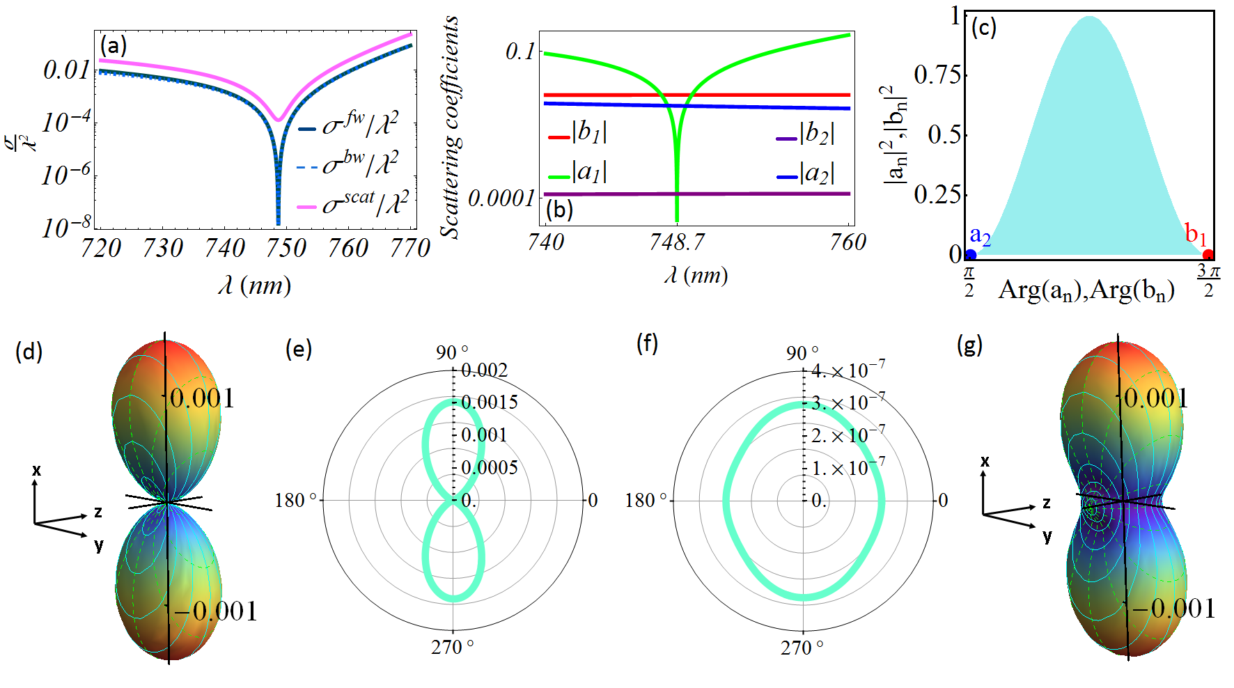
In addition to have 4 lowest multiple moments, another possibility to have NZFS and NZBS simultaneously is to have electric quadrupole and magnetic dipole only, with . To excite the magnetic dipole, we use titanium dioxide () in shell, gold () in middle, and silicon () in core for our three-layered nano-sphere. Now, the geometrical size parameters are chosen as nm, nm, and nm. Even though gold is a lossy material, at the first stage we embed material dispersions of these three composites into our calculation but without lossy terms handbook .
In Fig. 2(a), we report the corresponding spectra for forward, backward, and total scattering cross sections from our proposed structure. As one can see clearly, there is a dip at nm, at which both forward and backward scattering cross section approach zeros. The corresponding spectra for the lowest four multipole moments are also depicted in Fig. 2 (b). As we design, the electric dipole () is minimum at nm; while the dominant channels become and . The locations of and are shown in Fig. 2(c), which indicates a nearly phase difference between the magnetic dipole and electric quadrupole.
The resulting radiation patterns are illustrated in 3D plot, Fig. 2(d) and in 2D plots with (- plane), Fig. 2(e) or with (- plane), Fig. 2(f). The electrical permittivities used here are , , and for the shell, middle, and core regions, respectively. When the material loss is taken into consideration, the required phase difference will be destroyed, resulting in some uncanceled forward and backward scatterings, as illustrated in Fig. 2(g). We observe that with the lossy effect, the radiation pattern still remains a similar shape as that of a lossless one, but significant scatterings can be found in all directions.
Before conclusion, we want to remark that achieving such anomalous scatterers with NZFS and NZBS simultaneously, the material system can be composited without plasmonics. However, embedding HRI material in subwavelengthly scatterers is necessary, in order to excite quadrupole moments and magnetic response. As we known from optical theorem, it is impossible to meet the required conditions given in Eq. (5) perfectly. However, approaching a phase difference between the scattering coefficients still gives useful consequences. Even though, there are always other-order terms contributing to the end result, our direct numerical calculations illustrate good agreement with analytical results only with few lowest orders. Note also, that unwanted dipole response, for example, can be completely suppressed due to anapole type states excitations Miroshnichenko:NatComm:2015
In conclusion, we provide the required conditions to eliminate scattering at an arbitrary direction with the interferences among electrical/magnetic dipoles and quadrupoles. To go beyond Kerker’s conditions, we reveal the required conditions to support nearly zero forward scattering (NZFS) and nearly zero backward scattering (NZBF) simultaneously. By considering a three-layered nano-sphere at the sub-wavelength scale, we propose two different sets of composited materials, i.e., and as the shell/middle/core, for the experimental implementation in optical wavelengths. Our results can be readily applied for nano-antenna, directional emission control, and metasurfaces.
Funding.
Ministry of Science and Technology, Taiwan (MOST) (105-2628-M-007-003-MY4).
References
- (1) J. D. Jackson, Classical Electrodynamics (Wiley, New York, 1975).
- (2) P. Grahn, A. Shevchenko, and M. Kaivola, New J. Phys. 14, 093033 (2012).
- (3) M. Kerker, D.-S. Wang, and C. L. Giles, J. Opt. Soc. Am. 73, 765 (1983).
- (4) A. Alú and N. Engheta, J. Nanophoton. 4, 041590 (2010).
- (5) H. Ramachandran and N. Kumar, Phys. Rev. Lett. 100, 229703 (2008).
- (6) J. Y. Lee, A. E. Miroshnichenko, and R.-K. Lee, Phys. Rev. A 96, 043846 (2017).
- (7) B. Rolly, B. Stout, and N. Bonod, Opt. Express 20, 20376 (2012).
- (8) R. Paniagua-Domínguez, Y. F. Yu, A. E. Miroshnichenko, L. A. Krivitsky, Y. H. Fu, V. Valuckas, L. Gonzaga, Y. T. Toh, A. Y. S. Kay, B. Luk’yanchuk, and A. I. Kuznetsov, Nat. Commun. 7, 10362 (2016).
- (9) M. Decker, I. Staude, M. Falkner, J. Dominguez, D. N. Neshev, I. Brener, T. Pertsch, and Y. S. Kivshar, Adv. Opt. Mater. 3, 813 (2015).
- (10) A. I. Kuznetsov, A. E. Miroshnichenko, M. Brongersma, Y. S. Kivshar, and B. Luk’yanchuk, Science 354, 2472 (2016).
- (11) Y. S. Kivshar and A. E. Miroshnichenko, Opt. & Photon. News 28, 24 (2017).
- (12) S. Person, M. Jain, Z. Lapin, J. J. Sáenz, G. Wicks, and L. Novotny, Nano Lett. 13, 1806 (2013).
- (13) Y. H. Fu, A. I. Kuznetsov, A. E. Miroshnichenko, Y. F. Yu, and B. Luk’yanchuk, Nat. Commun. 4, 1527 (2013).
- (14) M. I. Tribelsky, J.-M. Geffrin, A. Litman, C. Eyraud, and F. Moreno, Sci. Rep. 5, 12288 (2015).
- (15) R. V. Mehta, R. Patel, R. Desai, R. V. Upadhyay, and K. Parekh, Phys. Rev. Lett. 96, 127402 (2006).
- (16) J. Y. Lee and R.-K. Lee, Opt. Express 24, 6480 (2016).
- (17) C. F. Bohren and D. R. Huffman, Absorption and Scattering of Light by Small Particles (Wiley, New York, 1998).
- (18) R. G. Newton, Am. J. Phys. 44, 639 (1976).
- (19) A. E. Miroshnichenko, Phys. Rev. A 80, 013808 (2009).
- (20) W. Liu, and Y. S. Kivshar, Opt. Express 26, 13085 (2018).
- (21) R. G. Chaudhuri and S. Paria, Chem. Rev. 112, 2373 (2011).
- (22) J.-Y. Lee, M.-C. Tsai, P.-C Chen, T.-T. Chen, K.-L. Chan, C.-Y. Lee, and R.-K. Lee, J. Phys. Chem. C 119, 25754 (2015).
- (23) E. D. Palik, Handbook of Optical Constants of Solids (Academic Press, New York, 1985).
- (24) A. E. Miroshnichenko, A. B. Evlyukhin, Y. F. Yu, R. M. Bakker, A. Chipouline, A. I. Kuznetsov, B. Luk’yanchuk, B. N. Chichkov and Y. S. Kivshar, Nat. Commun. 6, 8069 (2015).