A Factor Graph Approach to Multi-Camera Extrinsic Calibration on Legged Robots
Abstract
Legged robots are becoming popular not only in research, but also in industry, where they can demonstrate their superiority over wheeled machines in a variety of applications. Either when acting as mobile manipulators or just as all-terrain ground vehicles, these machines need to precisely track the desired base and end-effector trajectories, perform Simultaneous Localization and Mapping (SLAM), and move in challenging environments, all while keeping balance. A crucial aspect for these tasks is that all onboard sensors must be properly calibrated and synchronized to provide consistent signals for all the software modules they feed. In this paper, we focus on the problem of calibrating the relative pose between a set of cameras and the base link of a quadruped robot. This pose is fundamental to successfully perform sensor fusion, state estimation, mapping, and any other task requiring visual feedback. To solve this problem, we propose an approach based on factor graphs that jointly optimizes the mutual position of the cameras and the robot base using kinematics and fiducial markers. We also quantitatively compare its performance with other state-of-the-art methods on the hydraulic quadruped robot HyQ. The proposed approach is simple, modular, and independent from external devices other than the fiducial marker.
I Introduction
Robot calibration is a widely explored subject that involves the estimation of kinematics and camera intrinsic/extrinsic parameters, either by optical or mechanical methods.
Kinematics calibration adjusts robot parameters such as: link lengths, angle offsets and other body dimensions that are crucial for precise end-effector placement, especially in industry [1]. These adjustments are required due to imperfections in manufacturing of mechanical parts, their assemblies, and aging processes.
Intrinsic calibration retrieves the parameters of the so-called camera pinhole model, which projects 3D points in space onto the image plane of the camera. These parameters model the skewness of the CMOS elements, lens placement and the optical center offsets. Since the lenses have finite dimension and non-null thickness, the model is typically extended with additional parameters to compensate for tangential and radial distortions as well.
Finally, extrinsic calibration consists on finding the pose (i.e., translation and rotation) of the camera with respect to a specific object captured within its field of view. In robotics, it is also important to estimate the camera pose expressed in the robot base frame. We will refer to this process as robot-camera extrinsic calibration111This is similar to the so-called “hand-eye calibration”, where the relative pose between a camera mounted on an arm and a robotic hand has to be detected[2]. In our case, there is no actuated linkage between the camera and the base, even though leg kinematics is used to perform the calibration.. This tells the robot where its “eyes” are, enabling it to track external objects and achieve true spatial cognition. An estimate of this robot-camera extrinsic directly influences all tasks involving sensor fusion of proprioceptive and exteroceptive signals, including state estimation, mapping, planning, and control.
Unfortunately, estimating robot-camera extrinsic is not an easy task. In prototyping applications, sensors are often replaced with new models due to obsolescence, hence their mounting locations are not always known by CAD design. On the other hand, mature products will still suffer from wear and tear or manufacturing defects. Therefore, it is desirable to have an easy, fast and accurate method to automatically perform this type of calibration whenever possible.
In this paper, we propose a factor graph based approach to robot-camera calibration for multiple cameras mounted on a legged robot. Factor graphs have been successfully applied to several inference problems [3], such as: SLAM, 3D reconstruction, and spatiotemporal crop monitoring. This work shows how they are suitable to perform robot-camera extrinsic calibration as well.
The contributions of the paper can be summarized as follows:
-
•
We present a novel approach to multiple robot-camera calibration based on factor graph optimization; the factors are designed as constraints originated by kinematics and visual detections of fiducial markers mounted at the robot’s end-effector. The approach is modular and adaptable to any articulated robot with an arbitrary number of cameras and limbs;
-
•
We provide a quantitative comparison between our method and other state-of-the-art methods available to date. To the best of our knowledge, this is the first time such comparison is presented to the scientific community;
-
•
We deliver the implementation of this method as an open-source ROS package222See https://github.com/iit-DLSLab/dls_factor_graph_calibration.
The paper outline is the following: Section II presents the related works on extrinsic camera calibration for mobile robots; Section III formally describe the problem of robot-camera extrinsic calibration; Section IV describes our factor graph approach for extrinsic and multi-camera calibration; Section V states the result of this work and compares our methods with the state-of-the-art; Section VI summarizes the work, and points to future directions.
II Related work
Extrinsic calibration in robotics has been investigated since the introduction of visual sensors to industrial manipulators. In this section, we limit to the literature dedicated to mobile robots, which can be broadly divided into visual-kinematics methods and visual-inertial methods.
II-A Visual-Kinematics Methods
The most common extrinsic camera calibration technique for mobile robots use an external marker (i.e. a checkerboard) placed at the end-effector. The procedure demands to move the robot arm constantly, recognize marker key points, and estimate the relative transformations to the camera. The collected transformations allow to compare camera marker poses with the poses estimated through the kinematic chain, according to encoder values. Then, the cost function to be minimized is formulated as the reprojection error between the detected marker and its projection through the kinematic chain.
Pradeep et al. [4] proposed an approach based on bundle adjustment to calibrate the kinematics, lasers and camera placements on the PR2 robot. The optimization includes all transformations needed for the robot (sensors to sensors and sensors to end-effectors) and the measurement uncertainties are modeled as Gaussians. The major drawback of the procedure is the calibration time, which is 20 minutes onboard the PR2, plus 25 minutes for the offline nonlinear optimization. This largely limits the application during field operations.
More recently, Blöchlinger et al. [5] applied the same idea to the quadruped robot StarlETH. They used a couple of circular fiducial marker arrays attached to the front feet and minimized the reprojection error between the detected markers (with a monocular camera) and their projection using forward kinematics. The objective of the cost function includes a set of 33 parameters, including: link lengths, encoder offsets, time offsets, and also the robot-camera relative pose. Since the focus was more on finding the kinematics parameters, no results are shown for the robot-camera calibration. The performance on link lengths is assessed by comparison with the CAD specifications, yielding a margin of .
To reduce the uncertainty due to kinematics, in our previous work [6], we developed a method based on fiducial markers and an external capture system. The fiducial marker is not attached to the robot body, but it is placed externally, surrounded by a circular array of Motion Capture (MoCap) markers (small reflective spheres). The MoCap markers are also placed on the robot at a known location. When the camera detects the fiducial marker, the robot-camera affine transform is recovered from the chain formed by the camera-to-fiducial, the vicon-to-fiducial and the robot-to-vicon transforms. An obvious drawback of this method is the need of an expensive equipment for MoCap.
II-B Visual-Inertial Methods
In the visual-inertial calibration domain, the objective is the relative transformation between an IMU and a camera. If the relative pose between IMU and base link is known, this method is equivalent to robot-camera calibration. Since no kinematics is involved, the primary application is Micro-Aerial-Vehicles (MAVs): in this context, the different frequencies and time delays between inertial and camera data need to be taken into account [7].
Lobo and Dias [8] described a two-step, IMU-camera calibration procedure. First, they calculate the relative orientation by detecting the gravity vector with the IMU and the lines of a vertically placed marker with the camera. Then, the translation is calculated as the lever arm separating the two sensors, which are vertically aligned from the previous step and moved on a turntable. The main disadvantage of this method is its dependency on controlled setups, which are unavailable for sensors rigidly mounted on a mobile robot. Moreover, ignoring the mutual correlation between rotation and translation can lead to further errors.
Mirzaei and Rumeliotis [9] proposed a filter-based algorithm to overcome some limitations of [8]. The method is also two-step. First, they create a prior for the IMU-camera transform by using observations of an external marker for the camera pose and from manual measurement for the IMU pose, respectively. Second, they refine the initial guess by performing visual-inertial state estimation with an Extended Kalman Filter (EKF). The state includes: position and linear velocity of the IMU, the IMU biases, and the unknown transformation between the IMU frame and the camera frame. The authors also demonstrate that these states are observable.
Similarly to [9], Kelly et al. [10] proposed an approach based on the Unscented Kalman Filter (UKF), which has been tested both with and without prior knowledge of a calibration marker.
Furgale et al. [11] proposed an estimator for IMU-camera calibration that simultaneously determines the transformation and the temporal offset between the two sensors. In contrast to previous methods, the time-varying states are represented as the weighted sum of B-spline functions, so that the state can be considered continuous. Their proposed implementation, Kalibr, is publicly available and it has been included in our comparative study.
Visual-Inertial extrinsic calibration is independent from robot kinematics. However, it requires homogeneous and smooth excitation on all the IMU axes to perform well. Even though this is simple for small quadrotors (manually moved in the air), it becomes not trivial for large legged robots. Furthermore, the precise location of the IMU on the robot is assumed as known.
III Problem Statement
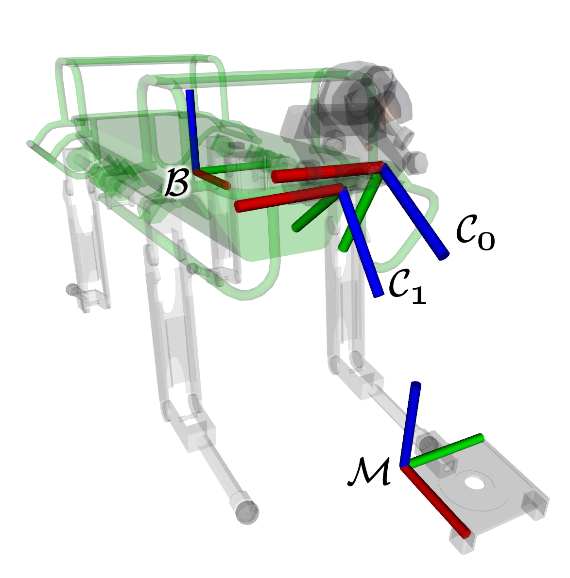
Let us consider a floating base, articulated robot with a main body, one or more limbs, and one or more cameras rigidly attached to the main body. Our goal is to retrieve the relative pose between the optical center of the cameras and the base frame on to the main body, by means of: a) kinematic constraints and b) the detection of a fiducial marker located at the end-effector of a limb, with frame (see Fig. 2a).
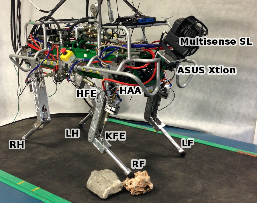
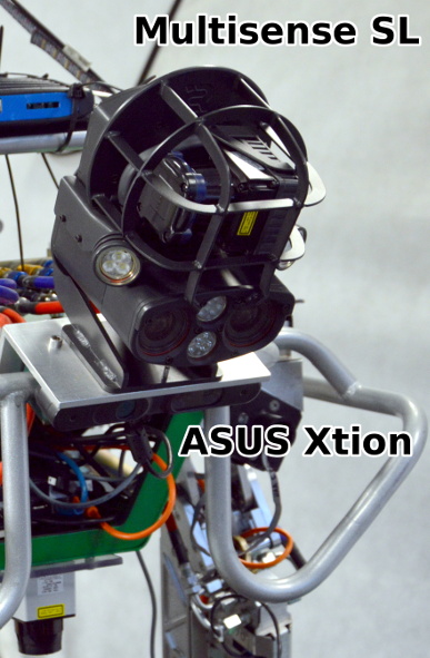
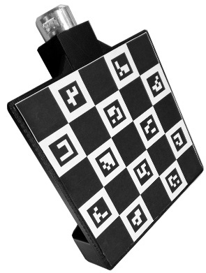
In this paper, we will consider the HyQ robot [12] as the experimental platform of choice. HyQ is a , long hydraulic quadruped robot with 12 actuated Degrees-of-Freedom (DoFs). Each leg has 3 DoFs (Fig. 1): the Hip Abduction-Adduction (HAA), the Hip Flexion-Extension (HFE) and the Knee Flexion-Extension (KFE). The reference frames are shown in Fig. 2a: the base frame is conventionally placed at the torso center, with the -plane passing through the HAA motor axes; the frames and are the optical frames of the Multisense SL’s left camera and the ASUS Xtion’s RGB camera, respectively; the marker frame is at the bottom right corner of the ChAruco fiducial marker [13] mounted on the tip of HyQ’s LF foot (Fig. 2b).
IV Multi-Camera Factor Graph Calibration
The factor graph for multi-camera calibration is shown in Fig. 3. In its general formulation, an array of cameras is mounted on the robot. Their pose from the base frame are expressed by the nodes .
The gray nodes denote the observed fiducial marker poses visible from the cameras over time (the cameras are not required to detect all the observations). We introduce two types of factors: the kinematics factors and the fiducial factors. The former are unary factors associated to the landmarks and express the kinematic constraints between the marker frame and the base frame by means of forward kinematics. The latter connect with and correspond to the relative pose between the fiducial marker and the camera.
For all measurements, a zero-mean Gaussian noise model is adopted, where the covariance is a diagonal matrix whose values are computed taking to account: a) the encoder uncertainty and their propagation to the end effector [14]; and b) the uncertainty on the vertex jitter of the marker detection [13]. After accumulating marker poses, a Gauss-Newton factor graph optimization is performed.
V Experimental Validation
We have implemented the graph from Section IV on the HyQ robot, using the GTSAM library [3]. Given the flexibility of the approach, new cameras or markers can be added just by including the corresponding nodes in the graph. The kinematics factors are given by the forward kinematics through the RobCoGen library [15]. The fiducial factors are implemented with the AruCo library [13], which is capable of sub-pixel accuracy and provides pose estimation markers (ChAruco).
In this section, we compare the performance of this approach with the MoCap-based method of [6] and Kalibr [11].
The ground truth was collected by physically constraining the robot to a known configuration and detecting a marker with a known pose (accurately measured with digital calibers and inclinometers) from the robot.
Table I shows the linear and angular Mean Absolute Error (MAE) obtained for the two cameras mounted on HyQ.
For Kalibr, we have collected a dataset of 2778 frames (), during which the robot was excited (either manually or with some actuation) on all axes. In general, the mean results are accurate (linear and angular errors for the Multisense SL are and , respectively), even though the effort to excite the robot properly makes the procedure difficult to repeat (hence the high standard deviation). We believe the low resolution of the ASUS is the major cause of the poorer results. With the kinematics calibration, the marker can get much closer to the camera, reducing this effect.
For the MoCap method, we collected 562 frames () of the static robot facing the marker. For the Multisense, the method shows a error in both translation and rotation. Since the MoCap has sub-millimeter accuracy, the marker placement (either on the robot and on the fiducial marker) is the major source of error.
To test the effect of multiple camera constraints, we tested the factor graph method both for individual cameras and with both cameras at the same time. We collected a dataset of 1312 images for a total duration of while the leg was passively moved in front of both cameras. In general, both method show slightly worse but more stable and balanced results than Kalibr. In particular, the mutual constraint between the cameras reduced the error for the Multisense setup from to on translation and from to in rotation (cf. F1 and F2 in Table I).
| Multisense SL | ||||||
|---|---|---|---|---|---|---|
| X () | Y () | Z () | Roll () | Pitch () | Yaw () | |
| [] | [] | [] | [deg] | [deg] | [deg] | |
| K | 0.2 (1.8) | 0.2 (1.4) | 1.8 (0.5) | 0.1 (0.3) | 0.8 (0.7) | 0.4 (0.6) |
| M | 1.3 | 1.4 | 1.8 | 1.0 | 0.3 | 0.4 |
| F1 | 1.1 (0.1) | 0.9 (0.5) | 2.1 (0.5) | 0.5 (0.2) | 0.2 (0.1) | 1.8 (0.5) |
| F2 | 1.2 (0.5) | 0.3 (0.5) | 1.0 (0.2) | 0.2 (0.5) | 0.6 (0.2) | 1.1 (0.2) |
| ASUS Xtion | ||||||
| K | 1.2 (1.8) | 3.1 (0.4) | 5.3 (0.5) | 2.9 (0.3) | 3.8 (0.7) | 2.5 (0.6) |
| F1 | 2.5 (0.3) | 0 (0.4) | 0.1 (0.2) | 0.9 (1.4) | 1.3 (0.2) | 2.1 (1.2) |
| F2 | 1.8 (0.4) | 0.6 (0.5) | 0.4 (0.4) | 0.8 (0.5) | 0.2 (0.1) | 0.2 (0.2) |
VI Conclusions and Future Work
In this paper, we have presented a factor graph approach to multi-camera calibration of a quadruped robot. We have demonstrated that a factor graph framework represents a valid and flexible alternative to visual-inertial methods, which require smooth motion and balanced excitation of all axes to provide reliable results. On the other hand, visual-kinematics methods require hardware modifications at the end-effector (i.e., a fiducial marker support) to be precise.
Future developments from this work are oriented towards the integration of both methods in a factor graph fashion to make the calibration even more robust and automated.
References
- [1] S. Y. Nof, Handbook of Industrial Robotics, 2nd ed. New York, NY, USA: John Wiley & Sons, Inc., 1999.
- [2] R. Horaud and F. Dornaika, “Hand-Eye Calibration,” The International Journal of Robotics Research (IJRR), vol. 14, no. 3, pp. 195–210, 1995.
- [3] F. Dellaert and M. Kaess, “Factor Graphs for Robot Perception,” Foundations and Trends in Robotics, vol. 6, no. 1-2, pp. 1–139, Aug 2017.
- [4] V. Pradeep, K. Konolige, and E. Berger, Calibrating a Multi-arm Multi-sensor Robot: A Bundle Adjustment Approach. Berlin, Heidelberg: Springer Berlin Heidelberg, 2014, pp. 211–225.
- [5] F. Blöchlinger, M. Blösch, P. Fankhauser, M. Hutter, and R. Siegwart, “Foot-Eye Calibration of Legged Robot Kinematics,” in Advances in Cooperative Robotics (CLAWAR), 2016, pp. 420–427.
- [6] M. Camurri, S. Bazeille, D. Caldwell, and C. Semini, “Real-Time Depth and Inertial Fusion for Local SLAM on Dynamic Legged Robots,” in IEEE International Conference on Multisensor Fusion and Integration for Intelligent Systems (MFI), Sep 2015, pp. 259–264.
- [7] J. Kelly, N. Roy, and G. S. Sukhatme, “Determining the Time Delay Between Inertial and Visual Sensor Measurements,” IEEE Transactions on Robotics, vol. 30, no. 6, pp. 1514–1523, Dec 2014.
- [8] J. Lobo and J. Dias, “Relative Pose Calibration Between Visual and Inertial Sensors,” The International Journal of Robotics Research, vol. 26, no. 6, pp. 561–575, 2007.
- [9] F. M. Mirzaei and S. I. Roumeliotis, “A Kalman Filter-Based Algorithm for IMU-Camera Calibration: Observability Analysis and Performance Evaluation,” IEEE Transactions on Robotics, vol. 24, no. 5, pp. 1143–1156, Oct 2008.
- [10] J. Kelly and G. Sukhatme, “Visual-Inertial Simultaneous Localization, Mapping and Sensor-to-Sensor Self-Calibration,” in IEEE International Symposium on Computational Intelligence in Robotics and Automation (CIRA), Dec 2009, pp. 360–368.
- [11] P. Furgale, J. Rehder, and R. Siegwart, “Unified Temporal and Spatial Calibration for Multi-Sensor Systems,” in IEEE/RSJ International Conference on Intelligent Robots and Systems (IROS), Nov 2013, pp. 1280–1286.
- [12] C. Semini, N. G. Tsagarakis, E. Guglielmino, M. Focchi, F. Cannella, and D. G. Caldwell, “Design of HyQ – a Hydraulically and Electrically Actuated Quadruped Robot,” Proceedings of the Institution of Mechanical Engineers, Part I: Journal of Systems and Control Engineering, vol. 225, no. 6, pp. 831–849, 2011.
- [13] F. J. Romero-Ramirez, R. Muñoz-Salinas, and R. Medina-Carnicer, “Speeded Up Detection of Squared Fiducial Markers,” Image and Vision Computing, vol. 76, pp. 38–47, Aug 2018.
- [14] R. Hartley, J. Mangelson, L. Gan, M. G. Jadidi, J. M. Walls, R. M. Eustice, and J. W. Grizzle, “Legged Robot State-Estimation Through Combined Forward Kinematic and Preintegrated Contact Factors,” in IEEE International Conference on Robotics and Automation (ICRA), May 2018, pp. 1–8.
- [15] M. Frigerio, J. Buchli, D. G. Caldwell, and C. Semini, “RobCoGen: a code generator for efficient kinematics and dynamics of articulated robots, based on Domain Specific Languages,” vol. 7, no. 1, pp. 36–54, 2016.