Multi-functional resonant acoustic
networks for wave routing
Abstract
We demonstrate that asymmetric 3-port devices can be used to design a multi-functional set-up operating as a symmetric combiner and splitter at the same frequency. For a concrete implementation of the proposed multi-functionality protocol, we employ a resonant acoustic 3-port device operating in a subwavelength regime, showing splitting/combining abilities with nearly perfect transmission in presence of losses, induced by the interactions of the system’s resonances. Finally, as an extension of the 3-port multi-functionality concept, we propose a new type of 4-port networks, consisting in an assembly of 3-port unit cells with combining/splitting properties, capable to achieve various wave guiding features with perfect transmission depending on the phase of the inputs.
Wave routing has always been a great challenge for many physical applications. Numerous works focus on the design of multi-port devices capable to guide waves from specific inlets to different outlets. Such devices include power divider or combiner (which divides or combines one or several inputs into several or one ports) or multiplexer systems which selects one of several inputs and transfers this input into a specific port. For example, in microwave engineering, guiding devices such as power dividers, circulators, filters couplers and multiplexer are commonly used Pozar . Multiport devices can be realized in different ways employing resonant structures Rosenberg ; Pozar ; Mouadili , photonic crystals Yu ; Park ; Shinya , metamaterials Tseng ; Ourir2 as well as waveguides with multimode interferences Han ; Sun . In electromagnetics, selected filters and multiplexers have also been implemented by using structured materials as nonuniform waveguide network Feigenbaum2010a ; Feigenbaum2010b and complex photonic circuits are studied and designed for optical signal processing or computing in integrated optics Parinaz .
In acoustics, two-port systems have been studied and different phenomena including Coherent Perfect AbsorptionMerkel ; Romero , reflectionless transmission Merkel2018 or perfect transparency Tao have been revealed. Nevertheless, it appears that only a few works are dealing with systems with more than two ports. As example, three-port systems based on resonant scatterers, have been proposed to achieve Coherent Perfect Absortion/Coherent Perfect Transmission Richoux2018 or channeling Zhang , by tuning the geometry of the system and the wave input. PT-symmetric three-port systems using spatiotemporal modulation or circulating fluid, have been employed to obtain non reciprocal acoustic circulator Fleury2015 ; Fleury2014 . Directional excitation, asymmetric reflection and wave router for multi-ports have been developed using metamaterials and/or PT-symmetric systems Fu ; ZhangAc ; Zhu ; Dai ; Ramezani . Finally, a splitter system has been realized using acoustic topological network He .
In this work, we demonstrate (both theoretically and numerically) that an acoustic resonant subwavelength three-port can be used to obtain a symmetric splitter and a symmetric combiner with a quasi perfect transmission despite the presence of losses in the system. The device is composed of identical connected waveguides side-loaded by resonant scatterers. The control of the wave is made possible using induced transparency resonance Mouadili coming from the interaction of the resonances of individual scatterers through the waveguide. Tuning these resonances, one can achieve wave guiding with almost perfect transmission. By arranging several 3-port systems with these specific properties, we propose an optimally designed network which allows for multiple functionalities illustrated here by a 4-port case. We design a directional coupler with prescribed wave guiding abilities depending on the relative phase of the input waves. We demonstrate using 3D simulation the feasibility of this device.
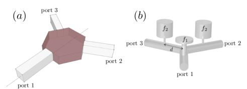
Let us consider a system connected to three identical input/output ports as shown in Fig. 1(a), exhibiting mirror symmetry with respect to one port e.g port 1 in Fig. 1(a).
Assuming single mode propagation in each channel, we may write the corresponding scattering matrix as
| (1) |
and are the complex, frequency dependent, reflection and transmission coefficients from port 1 while and are the reflection and transmission coefficients from port 2 or 3. In Eq. (1) the vectors and
describe the incoming and outgoing waves respectively, while the numbering denotes the corresponding port.
Tuning the reflection and transmission coefficients allows us to
achieve a system with prescribed functionalities at an operating frequency .
Here we are interested in designing a 3-port system that acts simultaneously as a symmetric splitter and a symmetric combiner with perfect transmission at this operating frequency .
Conditions for Symmetric Splitter: We consider an input from port 1. We want this to be equally transmitted to ports 2 and 3 without loss at the frequency . We thus first require that there is no reflection, namely:
| (2) |
At the same time, we require perfect transmission at the same frequency . For this, we demand the scattering matrix to be unitary, satisfying the following relation (where is the conjugate transpose of and is the identity matrix) which further constraints its elements as follows
| (3) | |||
| (4) |
Thus, Eqs. (2-4) present the conditions to achieve a symmetric splitter from port 1 with a perfect transmission (no loss).
Conditions for Symmetric Combiner: The symmetric combiner is simultaneously achieved from the same above conditions. Indeed, Eq. (1) combined with Eq. (3) ensures that an input defined by and is only guided to the remaining channel since we obtain (it is a consequence of the time reversal symmetry) at the frequency . In the same time, the perfect transmission is ensured by the Eq. (4). As a consequence of these conditions, we directly obtain . It is also interesting to remark that by imposing conditions for symmetric splitter with perfect transmission, we obtain directly the symmetric combiner property. Note that the proposed constraints could be achieved in system supporting different kinds of waves e.g. optical, electrical, acoustical or quantum.
In this work, we implement such a device using a 3-port acoustic structure made of three identical waveguides connected by a symmetric Y-connection [see Fig. 1(b)]. Each waveguide is side-loaded by a Helmholtz resonator (HR) at a distance from the Y-connection. The HRs are characterized by their resonance frequencies and their inherent losses (viscous and thermal effects at the boundaries) depending on their geometry. The symmetry of the system can be controlled by tuning the resonance frequencies of the HRs. Here we choose that the first waveguide is side-loaded by a HR with resonance frequency while the other two by a HR with a resonance .
For sufficiently low frequencies (below the first cut-off frequency of the waveguide where only the plane mode is propagative) the acoustic device is characterised by a scattering matrix of the form of Eq. 1. The coefficients , , and are analytically determined using the Transfer Matrix Method (TMM) where the visco-thermal losses in the waveguides and in the resonators are taken into account Richoux2018 . These coefficients depend both on frequency and on the geometrical characteristics of the structure e.g. the distance , necks and cavities of the HRs, etc. Below we use these analytical expressions in order to obtain the proper configuration whose coefficients satisfy Eqs. (2)-(4), by performing a numerical optimization based on simplex derivative free method Nelder-Mead opt at a prescribed operating frequency of Hz.
The optimized geometrical parameters are given in opto achieving a convergence up to 97%. The analytical expressions of the coefficients are presented in Fig. 2 where the gray line corresponds to , the black line to and the red one to satisfying Eqs. (2-4) at the operating frequency Hz. Indeed the analytical results give and and consequently and . This optimized 3-port device is achieved through the induced transparency resonance Mouadili , localized between two transmission zeros, coming from the interaction of the detuned resonances of each HR. These resonances correspond to the two peaks in and (or dips in ) at Hz and Hz surrounding the operating frequency.
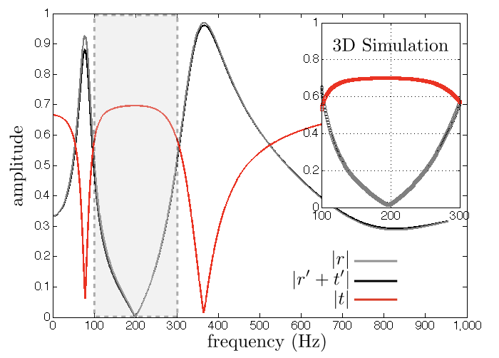
To verify the above analytical results obtained using the TMM method, we compared them with 3D FEM simulation with visco-thermal losses at the boundaries of the system (walls of the waveguides and resonators). The results of the simulation are shown in the inset of Fig. 2 for a frequency range from Hz to Hz as highlighted by the gray area. The operating frequency is found at Hz very close to the analytical one Hz. This small disagreement is essentially due to the 1D assumptions (monomode propagation in the waveguide and no evanescent waves around the scatterers) of the analytical model.
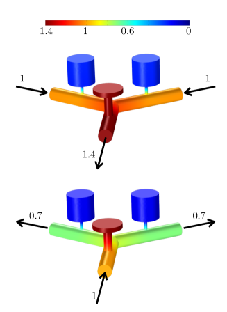
In addition the HRs are considered as point scatterers in the model whereas in the FEM simulation, their sizes are small but finite. For illustration purposes, using the data from the simulation, we show both the splitting and the combining operation in Figs. 3(a) and 3(b) respectively at the operating frequency Hz. When [see Fig. 3(a)], we find that and validating that the system acts as a symmetric combiner with almost perfect transmission. Furthermore when only the port is illuminated [see Fig. 3(b)] with , the wave is guided to ports 2 and 3 with an amplitude given by possessing splitter property. Due to the fact that we choose HRs as scatterers, the operations of the optimized 3-port occur in a subwavelength regime. More precisely, for the acoustic set-up described here where is the wavelength at the operating frequency.
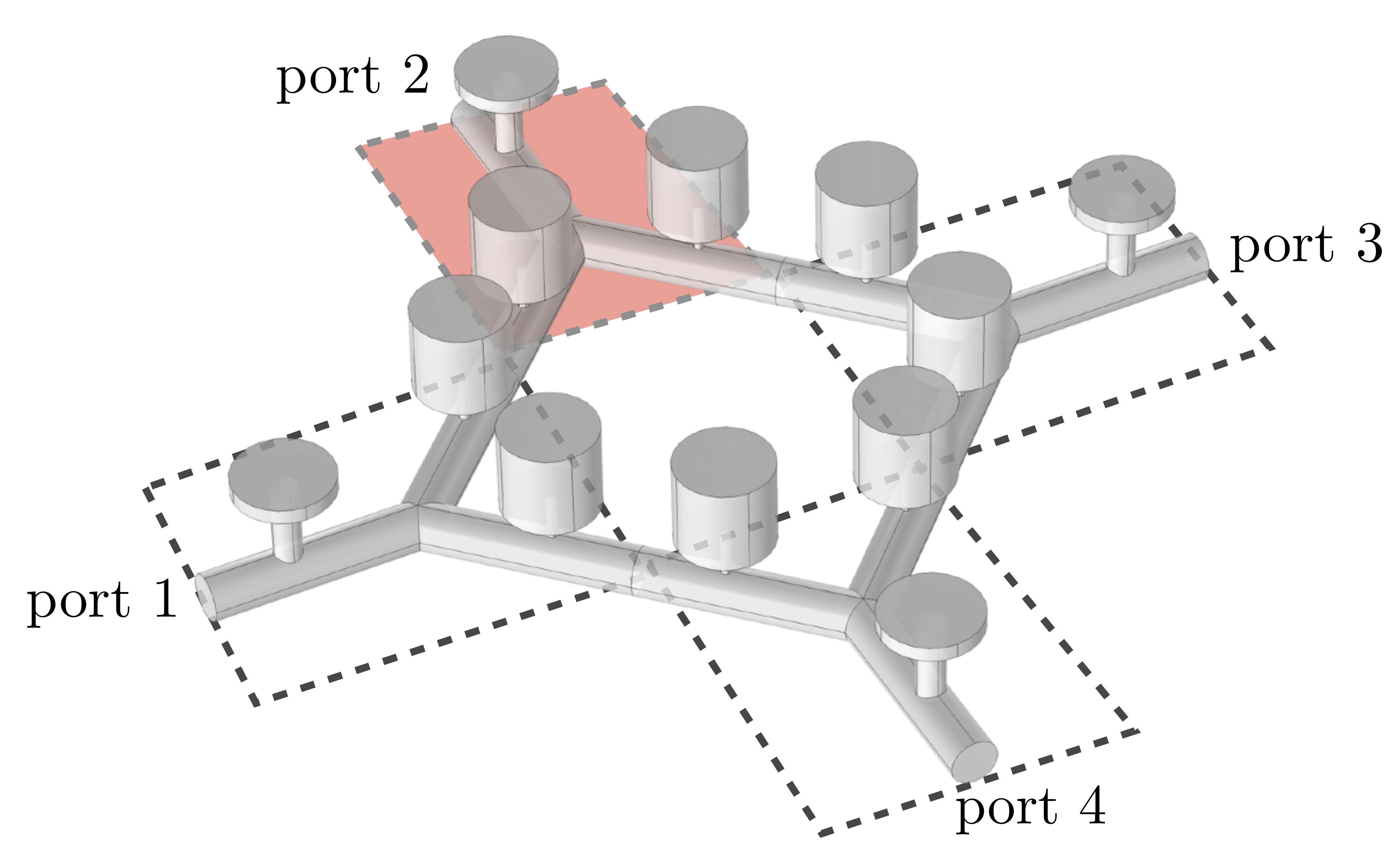
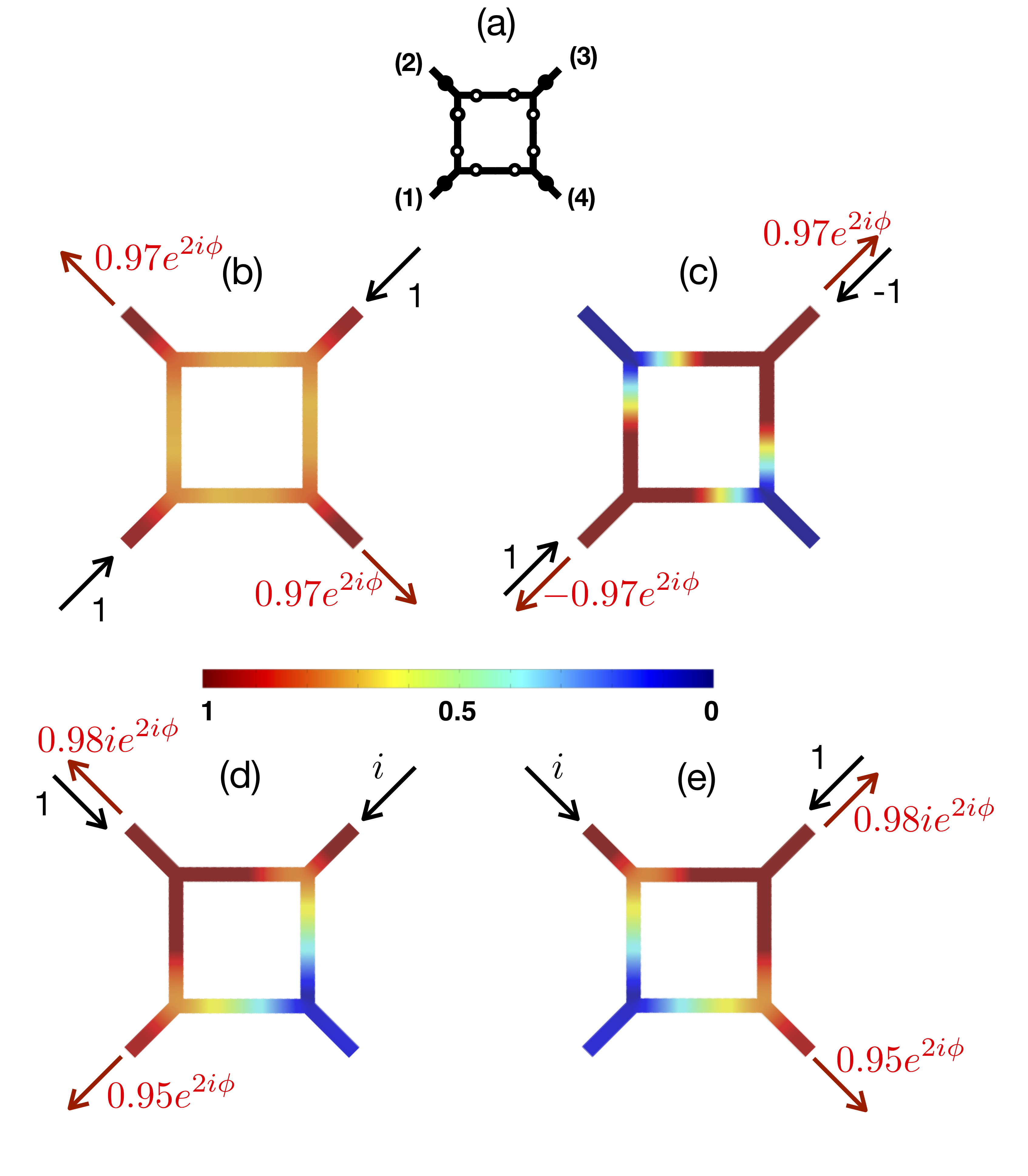
The great advantage of this device, with the same waveguide’s section at each port (as opposed to other alternatives i.e. Zhang ) is that we can easily design a plethora of multi-port network configurations by connecting 3-port blocks. Using the simple characteristics of this elementary cell, we can assigne specific properties to the scattering matrix of the network by choosing the orientation of each block. To illustrate this, among the numerous possible configurations, here we study a network composed by 4 identical blocks as illustrated in the Fig. 4. The resulting 4-port device features C4 symmetry due to the chosen orientation of the building blocks. We arrange the unit-cells such as the HRs with resonance are located on the external branches while the rest HRs with resonance are in the internal ring depicted in Fig. 5(a) with black and white dots respectively. Below we illustrate that such a network may acquire different routing operations at the prescribed frequency selected by the input configuration.
Using the star product, the scattering matrix of this 4-port network is determined by the elements of the 3-port scattering matrix given in Eq. 1 as we show in detail in the supplementary material. Since we assume that our 3-port building blocks act as splitters/combiners with a nearly perfect transmission, Eqs. (2-4) are satisfied, and the 4-port scattering matrix can be simplified to the following form at frequency
| (5) |
where is the phase of . To obtain Eq. (5) we add an additional condition on the phase of (see supplementary material) which is easily achieved by changing the waveguide length of the 3-port building blocks. This network, satisfying Eq. (5), owing to the chosen orientation of the building blocks, is able to perform four different kinds of routing operation with an almost perfect transmission at the same frequency solely by changing the input vector.
The first two operations concern the scattering from two diagonal ports with waves of the same amplitude but differing in phase. When the phase of the two inputs is equal, the device can route waves from two diagonal ports to the other two acting as an orthogonal directional coupler. To illustrate this functionality at the prescribed frequency , we perform 3D FEM simulation with an input of the form . As shown in Fig. 5(b), the wave is equally guided towards the ports 2 and 4 with an almost perfect transmission since we find and . On the other hand, when diagonal ports are excited by waves of the same amplitude but opposite phase then the network becomes transparent, i.e. the remaining ports are muted. This is also confirmed by the simulations results shown in Fig. 5(c) with , and . Note that, as indicated in Figs. 5(b)-(c), the relative phase between the outputs is the same as for the inputs.
The additional operations of the network satisfying Eq. 5 concern the scattering from two consecutive ports with waves of equal amplitude and varying phase. For example when the input is defined by , as shown in Fig. 5(d), the input waves from ports 2 and 3 are guided to ports 1 and 2 leaving the port 4 muted. Thus the device acts as a counter-clockwise directional coupler with an almost perfect transmission as found by the numerical results achieving and . When the inputs are inverted, i.e. , the operation of the network is also reversed and it acts as a clockwise directional coupler. This functionality is illustrated in Fig. 5(e). Once again, the relative phase of the inputs is inherited to the outputs. Note that, due to the symmetry of the system, these functionality holds for any two consecutive ports.
This work proposes the design of complex networks using subwavelength splitter/combiner 3-port systems as the network building blocks. Thus, we are able to manipulate the coefficients of the scattering matrix of a complex network to obtain prescribed wave routing by playing with orientation and characteristics of the 3-port unit-cell. Aiming at particular wave routing operations, we construct a compact 4-port network by connecting four of the aforementioned building blocks in a symmetric orientation. The resulting network is capable of guiding incident waves to different outgoing channels, i.e. orthogonal, clockwise and counter-clockwise directional couplers, selected only by the relative phase of the input. Alternative input/output functionalities, could also be achieved by connecting the building blocks with different orientations. This concept of designing networks with multi-functionalities can also be applied for wave routing or filtering in different domains of physics as acoustics, electromagnetisms, optics or microwaves.
This work is supported by “Le Mans Acoustique” and funded by the “Pays de la Loire” French Region and the “European Regional Development Fund”. I.B. research is financed by the project CS.MICRO funded under the program ”Etoiles Montantes” of the “Pays de la Loire” French Region.
References
- (1) D. M. Pozar, Microwave Engineering, third edition, John Wiley & Sons, 2004.
- (2) U. Rosenberg, M. Salehi, J. Bornemann and E. Mehrshahi, A Novel Frequency-Selective Power Combiner/Divider in Single-Layer Substrate Integrated Waveguide Technology, IEEE Microw. Wireless Comp. Lett., 23, 406, 2013.
- (3) A. Mouadili, E. H. El Boudouti, A. Akjouj, H. Al-Wahsh, B. Djafari-Rouhani and L. Dobrzynski, Y-shaped magnonic demultiplexer using induced transparency resonances. AIP Advances, 9(3), 035011, 2019, doi: 10.1063/1.5080350.
- (4) Tian-Bao Yu, Ming-Hua Wang, Xiao-Qing Jiang, Qing-Hua Liao and Jian-Yi Yang, Ultracompact and wideband power splitter based on triple photonic crystal waveguides directional coupler, J. Opt. A: Pure Appl. Opt. 9, 37–42 (2007).
- (5) I. Park, H-S. Lee, H-J. Kim, K-M. Moon, S-G. Lee, B-H. O, S-G. Park and E-H. Lee Photonic crystal power-splitter based on directional coupling, Opt. Express 12, 3599 (2004).
- (6) A. Shinya, S. Mitsugi, E. Kuramochi, and M. Notomi, Ultrasmall multi-channel resonant-tunneling filter using mode gap of width-tuned photonic-crystal waveguide, Opt. Express 13, 4202-4209 (2005), DOI: 10.1364/OPEX.13.004202.
- (7) A. Ourir, A. Maurel and V. Pagneux, Tunneling of electromagnetic energy in multiple connected leads using -near-zero materials. Optics letters, 38(12), 2092-2094, 2013, DOI: 10.1364/OL.38.002092.
- (8) C-H. Tseng and C-L. Chang, A Broadband Quadrature Power Splitter Using Metamaterial Transmission Line, IEEE Microw. Wireless Comp. Lett., 18, 25 (2008).
- (9) Y. Sun and A. P. Freundorfe, Multimode Interference-Based Photonic Crystal Waveguide Power Splitter, IEEE Microw. Wireless Comp. Lett., 14, 295, 2004.
- (10) Z. Han, S. He, Multimode interference effect in plasmonic subwavelength waveguides and an ultra-compact power splitter, Appl. Phys. Lett. 111, 122401 (2017); DOI: 10.1063/1.4987007.
- (11) E. Feigenbaum, S. P. Burgos and H. A. Atwater, Programming of inhomogeneous resonant guided wave networks, Opt. Express 25, 25584 (2010)
- (12) E. Feigenbaum and H. A. Atwater, Resonant Guided Wave Networks Phis. Rev. Lett. 104, 147402 (2010).
- (13) P. Aleahmad, M. Khajavikhan, D. Christodoulides and P. LiKamWa, Integrated multi-port circulators for unidirectional optical information transport. Scientific reports, 7(1), 2129, 2017, DOI:10.1038/s41598-017-02340-9.
- (14) A. Merkel, G. Theocharis, O. Richoux, V. Romero-García and V. Pagneux, Control of acoustic absorption in one-dimensional scattering by resonant scatterers. Applied Physics Letters, 107(24), 244102, 2015.
- (15) V. Romero-Garcia, G. Theocharis, O. Richoux, A. Merkel, V. Tournat and V. Pagneux, Perfect and broadband acoustic absorption by critically coupled sub-wavelength resonators. Scientific reports, 6, 19519, 2016.
- (16) A. Merkel, V. Romero-García, J. P. Groby, J. Li and J. Christensen, Unidirectional zero sonic reflection in passive PT-symmetric Willis media. Physical Review B, 98(20), 201102, 2018.
- (17) Z. Y. Tao, T. Liu, C. Zhang Y. X. Fan, Acoustic extraordinary transmission manipulation based on proximity effects of heterojunctions. Scientific reports, 9(1), 1080, 2019.
- (18) O. Richoux, V. Achilleos, G. Theocharis and I. Brouzos, Subwavelength interferometric control of absorption in three-port acoustic network. Scientific reports, 8(1), 12328, 2018, DOI:10.1038/s41598-018-30287-y.
- (19) X. Zhang,C. Meng and Z.Yang, Wave Manipulations by Coherent Perfect Channeling, Sci. Rep., 7: 13907, 2017, DOI:10.1038/s41598-017-14422-9.
- (20) R. Fleury, D. L. Sounas, C. F. Sieck, M. R. Haberman, A. Alù, Sound Isolation and Giant Linear Nonreciprocity in a Compact Acoustic Circulator, Science, 343, 516, 2014.
- (21) R. Fleury, D. L. Sounas, and A. Alu, Subwavelength ultrasonic circulator based on spatiotemporal modulation, Phys. Rev. B 91, 174306, 2015, DOI:10.1103/PhysRevB.91.174306.
- (22) Y. Fu and Y. Xu, Asymmetric effects in waveguide systems using PT symmetry and zero index metamaterials, Sci. Rep., 7, 12476, 2017, DOI:10.1038/s41598-017-12592-0.
- (23) T. Zhang, Y. Cheng, B-G. Yuan, J-Z. Guo and X-J. Liu, Compact transformable acoustic logic gates for broadband complex Boolean operations based on density-near-zero metamaterials, Appl. Phys. Lett. 108, 183508 (2016); https://doi.org/10.1063/1.4948655.
- (24) Y-F. Zhu, Z-M Gu, B. Liang, J. Yang, J. Yang, L-L. Yin and J-C. Cheng, Asymmetric sound transmission in a passive non-blocking structure with multiple ports, Appl. Phys. Lett., 109, 103504 (2016) DOI:10.1063/1.4962435
- (25) H. Dai, T. Liu, B. Xia and D. Yu, Quasilossless acoustic transmission in an arbitrary pathway of a network, Phys. Rev. B 95, 054109 (2017), DOI: 10.1103/PhysRevB.95.054109.
- (26) H. Ramezani, M. Dubois, Y. Wang, Y R. Shen and X. Zhang, Directional excitation without breaking reciprocity, New J. Phys. 18, 095001, 2016, doi:10.1088/1367-2630/18/9/095001.
- (27) C. He, X. Ni, H. Ge, X-C. Sun, Y-B. Chen, M-H. Lu, X-P. Liu and Y-F. Chen, Acoustic topological insulator and robust one-way sound transport, Nat. Phys. 12, 1124 (2016); DOI: 10.1038/NPHYS3867.
- (28) J. C. Lagarias, J. A. Reeds, M. H. Wright and P. E. Wright, Convergence Properties of the Nelder-Mead Simplex Method in Low Dimensions,SIAM Journal of Optimization. 9(1), 112–147 (1998).
- (29) The dimensions of HR1 are: length of the neck m, radius of the neck m, length of the cavity m and radius of the cavity m. The dimensions of HR2 are: length of the neck m, radius of the neck m, length of the cavity m and radius of the cavity m. The radius of the main waveguides is m. The distance between each HR and the central connection is with m the length of each waveguide.