Radiation of fast positrons interacting with periodic microstructure on the surface of a crystal
Abstract
Radiation of charged particles passing through a set of equidistant ridges on the surface of a single crystal is calculated. The ridges are rectangular in shape, each of thickness of half of the particle trajectory period at planar channeling in a thick crystal. Positively charged particle entering the first ridge with angle smaller than the critical channeling angle is captured into channeling and changes the direction of its transversal velocity to reversed. Between the half-wave ridges the particle moves along a straight line. Passing through such set of half-wave crystal plates the particle moves on quasi-undulator trajectories. Properties of the particle radiation emitted during their passage through such “multicrystal undulator” are calculated. The radiation spectrum in each direction is discrete, and the frequency of the first harmonic and the number of harmonics in the spectrum depends on the distance between the plates, on energy of the particles and on the averaged potential energy of atomic planes of the crystal. The radiation is bound to a narrow cone in the direction of the average particle velocity and polarized essentially in a plane orthogonal to the atomic planes of the crystal.
keywords:
channeling, radiation, half-wave crystal, relativistic particles, spectrum1 Introduction
Relativistic particles channeled in a single crystal have long been used as a source of hard electromagnetic radiation. One of the drawbacks of such a source is the limited ability of tuning the frequency of radiation. To address this shortcoming various schemes were proposed, which combine the advantages of channeling radiation and undulator radiation. The most common schemes include periodically bent crystals. The crystallographic planes can be bent by means of ultrasonic waves [1, 2] or periodic microscopic cuts of a single-crystal plate, which in this case is bent due to internal stresses [3, 4, 5, 6]. In order to get high energy radiation the crystal undulators were offered [7, 8] and then realized [9, 10] with the period much shorter than the period of particle channeling, and the bending amplitude much less than the spacing between the crystallographic planes.
In some cases, on the contrary, it is required to obtain more soft radiation, however, it is desirable to use a beam of sufficiently high energy particles to generate radiation of high intensity. For this purpose one can use either periodically bent crystal, or as proposed in [11], a set of thin crystalline plates, each changing the transversal velocity of the beam to reversal one, so that the particle trajectory in the set of the crystals looks like a zigzag line. Calculation of radiation in such a device referred to as a multicrystal undulator, is the focus of this paper.
The trajectories of electrons and positrons in a crystal plate of thickness equal to half of the particle trajectory period at planar channeling are investigated by numerical methods in [12]. Experimental study of the passage of electrons through such a half-wave plate is described in paper [13]. The radiation emitted in a single half-wave plate was studied numerically and it was shown that the basic properties of radiation are similar to those of radiation from the arc of a circle [14, 15]. Coherent superposition of the radiation fields generated in a series of half-wave plates results in the emission spectrum with specific properties that are studied theoretically in this paper.
2 The particle trajectory
Consider a multicrystal undulator constructed on the surface of a single crystal as shown in Fig. 1. It consists of a set of equidistant ridges rectangular in shape and each of half-wave thickness. The crystal planes which enable the channeling of positively charged particles, are orthogonal to the surfaces of the ridges. The height of the ridges is much greater than their thickness, hence, the rest of the crystal can be neglected. Hereafter we consider the ridges as a set of thin crystal plates. Similar design was used in experiments [16, 17] for production of diffracted X-ray transition radiation and parametric X-ray radiation at Bragg angle, but the thickness of the ridges was much greater than half of the channeling period.

We choose a coordinate system in such a way that the -axis is parallel to, and the -axis is orthogonal to the crystal planes. -axis is perpendicular to the initial velocity of the incident particle. The thickness of each plate is , the spacing between the plates is , and the distance between crystal planes equals . We use harmonic approximation for the average potential of the electric field between the crystal planes:
| (1) |
where is the depth of the potential valley. The relativistic equations of motion of the particle in the plane have the form
| (2) |
Here and are the momentum components
and are the mass and the charge of the particle, , the dot denotes the time derivative, is the speed of light.
Let the particle be ultrarelativistic () and the conditions of the dipole approximation are fulfilled [18]
| (3) |
where is the amplitude of variation. In this case the value of can be considered as a constant. Integration of the equations (2) in the adopted approximation gives
| (4) |
where and are the initial particle velocity and its -component, is the frequency of the particle oscillations
| (5) |
The condition of channeling is that the amplitude of oscillations must be less than half of the distance between the crystal planes. Hence, if a parallel beam of particles is incident upon the surface of the crystal plate, only particles with initial coordinate satisfying the condition
| (6) |
will be captured into the channeling mode. The remaining particles have above-barrier transverse energy. It follows from the above inequality that the initial transverse velocity must satisfy condition . If we introduce the angle of incidence as , the last inequality can be written as a well known Lindhard condition
| (7) |
The thickness of each crystal plate is equal to half of the trajectory period: . Hence, the -coordinate of the particle as it leaves the first crystal plate is , and the -component of the velocity is equal to . Between the first and the second crystal plates the particle moves along a stright line. If we require that all the particles deflected by the first plate are captured into channeling by the second plate, the particle coordinate at its incident on the second plate must satisfy condition similar to (6). This means that the transversal shift of the particle between the plates must make up a integer number of the distance between the crystal planes. This imposes the following condition on the distance between the plates
| (8) |
Hereafter we suppose that this condition is fulfilled. Then the law of the particle motion within the second crystal plate has the form
| (9) | ||||
| (10) |
where . If the angle of incidence is zero, then all the particles of the beam will be captured into channeling regardless of the distance .
The first two crystal plates and two subsequent gaps make up the spatial period of the multi-crystal undulator. The time period of motion is equal to .
3 Radiation
Spectral and angular distribution of the energy radiated by the particle at quasi-periodic motion along a plane trajectory is given by formula [18]
| (11) |
where is the number of periods of the undulator, the angular distributions of the polarization components and are defined by equations
| (12) |
and the Fourier component of acceleration is given by
| (13) |
Here is the frequency of the particle oscillations, , is the angle between the direction of radiation and the channeling axis (-axis), is the azimuthal angle in -plane .
Calculating the acceleration by use of equations (4) and (10) and substituting it in equations (11) and (13), we obtain
| (14) |
where is the ratio of the angle of incidence to the critical angle of channeling, and is the ratio of the frequency of particle oscillations to the frequency of oscillation at channeling (similar to duty cycle in electronics). The spectral functions
| (15) |
define essential properties of radiation. In case the function generates a narrow spectral lines of width in the neighborhood of odd values of , while the function is a spectral envelope. Fig. 2 shows the function (dashed line) and the product (solid line) for .
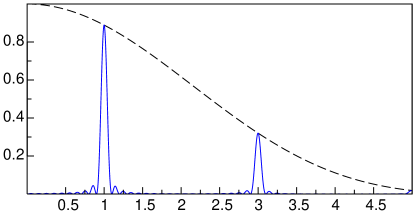
Function determines the width of the radiation spectrum (the number of harmonics represented in the spectrum). It follows from definition that function has its first zero where . If the distance between the crystal plates is equal to zero, i.e. if the particle is channeling in a solid crystal, then . In this case and only the first harmonic is presented in the emission spectrum. The number of harmonics in the spectrum increases with the reduction of . The frequency of the first harmonic of radiation of ultra-relativistic particles is determined by equation (13):
| (16) |
Let us find the spectral density of radiation. We calculate it for crystal undulator with large number of periods . Using the limit [18]
| (17) |
and integrating over the solid angle , we obtain the integral spectrum of radiation
| (18) |
where is the sum of the components of linear polarization
is a reduced frequency, and defines the influence of initial coordinate and the incidence angle on the spectrum:
is the Heaviside step function.
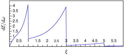
The emission spectrum (18) is represented as a sum of discrete harmonics as shown in Fig, 3. The shape of each harmonic defined by the polarization components and coincides with the well-known profile of undulator radiation in the dipole approximation [18, 19]. Distribution of the radiation energy in harmonics, as can be seen from the form factor , essentially depends on the angle of incidence of the particle in the crystal plate, its initial coordinate and the distance between the plates.
So far we investigated the properties of radiation of a single particle. In order to find the spectral density emitted by a parallel beam of particles we average the expression (18) over the initial coordinate through the interval given by equation (6). Since is represented only in , it will suffice to average only this multiple
| (19) |
and use instead of in equation (18). The spectrum of radiation of parallel beam of particles for parameters and is plotted in Fig, 3. For the purpose of comparison with the possible experimental results the same graph is shown in Fig. 4 as the number of photons per frequency interval . The spectrum consists in this case mainly of the first and third harmonics.
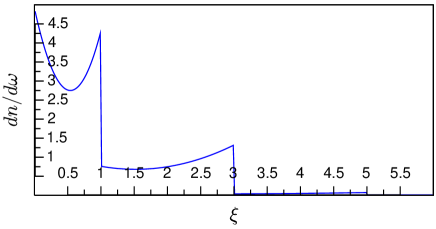
The number of harmonics, making the greatest contribution to the emission spectrum is determined by the factor , which is close to unity in the domain of low and decreases rapidly if . Thus, the main part of the spectrum contains about harmonics. Furthermore, the emission spectrum depends on the angle of incidence of the particle beam on the crystal. To explore this issue in more detail, let us find the energy of the radiation at each harmonic by integration of the expression (18) over within a single harmonic. Taking into account the replacement of we obtain the following
| (20) |
The distribution of emitted energy over the harmonics is given by the function
| (21) |
This is a discrete function of odd integer values of . The envelopes of this function for different angles of incidence are shown in Fig.5
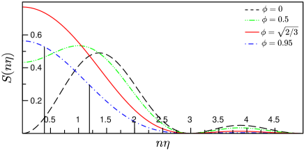
The dependence of the emission spectrum of the relative angle is presented only in the factor . If , this factor takes the value . As the angle of incidence increases, the value of increases in the low-frequency part of the spectrum () and reaches its maximum at
| (22) |
On further increasing of this function decreases and vanishes at . In the high-frequency part of the spectrum () the function decreases monotonically to zero with increasing of the angle of incidence.
Summing up equation (20) over the harmonics we obtain the total energy emitted by the beam of particles, per particle
| (23) |
which does not depend on and is distributed between the polarization components according to the ratio of 1:7. As a function of the angle of incidence, the emitted energy is a maximum at , i.e., when the angle of incidence is times less than the critical angle of channeling.
4 Discussion
If a source of radiation with a frequency less than the frequency of radiation at channeling is needed, the proposed method has certain advantages compared with radiation at channeling emitted by less energetic particles. Indeed, if you want to reduce the frequency of radiation of a channeling particles times, you have to use particles with energy times less. This will cause the cone of radiation to increase times, and spectral-angular density (14), which is proportional to , to decrease times. In the case of multi-crystal undulator the same decrease in frequency can be achieved if the distance between the crystal plates is equal to . Therewith the cone of radiation is not changed, and the spectral-angular density of radiation can both increase or decrease dependent on the angle of beam incidence.
There is an interesting peculiarity of the spectral-angular density of radiation. If the distance between the crystal plates increases, then the frequency of radiation on each harmonic decreases, and the number of harmonics represented in the main part of the spectrum () increases in the same ratio. According to equation (23) the total emitted energy does not depend on . Hence the energy emitted at each harmonic decreases as it is indicated by factor in equation (20). However, the spectral-angular density and the spectral density does not necessary decrease with , because there is not an -factor in equations (14) and (18). This is also seen from Fig. 3: as decreases, the scale-factor of -axes changes and the cut-off edge of each harmonic moves to the left in terms of . This definitely leads to decrease of the area under the curve representing the spectrum. But the spectral density itself changes slowly according to the terms of the sum in equation (18). If , then with the decrease of the spectral-angular and the spectral density of radiation at each harmonic is growing, despite the emergence of additional harmonics.
We have considered an idealized model in order to investigate the general properties of radiation. For example, the averaged potential in the vicinity of the crystal plane is not harmonic. As a result, the particles channeling with high amplitude of oscillations will have a smaller spatial period and will leave the ‘half-wave’ crystal plate at another angle. In other words, the plate being half-wave for some particles will not be such for others. This will cause slight scattering of the originally parallel beam of particles. Indeed, modeling of the trajectories in a more realistic potential shows that after the passage of a half-wave plate two side maxima in the angular distribution of the beam appear[12]. This and some other factors, such as a finite number of undulator periods, the energy spread of the particles in the beam, errors in manufacturing, will lead to broadening of the spectral lines and to blurring of the boundaries between the harmonics shown in Fig. 3. At the same time, these factors do not change significantly the distribution of radiation energy over the harmonics.
Acknowledgments
This work was supported by a grant of the Ministry of Education and Science of the Russian Federation under project no. 3.867.2014/K
References
- [1] V. Kaplin, S. V. Plotnikov, S. A. Vorobiev, Radiation by charged particles channeled in deformed crystals, Zh. Tekh. Fiz. 50 (1980) 1079.
- [2] V. Baryshevsky, I. Dubovskaya, A. Grubich, Generation of -quanta by channeled particles in the presence of a variable external field, Phys. Let. A 77 (1) (1980) 61–64. doi:10.1016/0375-9601(80)90637-4.
- [3] V. Baryshevsky, V. Tikhomirov, Crystal undulators: from the prediction to the mature simulations, Nucl. Instrum. Methods Phys. Res., Sect. B 309 (2013) 30–36. doi:10.1016/j.nimb.2013.03.013.
- [4] E. Bagli, L. Bandiera, V. Bellucci, A. Berra, R. Camattari, D. D. Salvador, G. Germogli, V. Guidi, L. Lanzoni, D. Lietti, A. Mazzolari, M. Prest, V. Tikhomirov, E. Vallazza, Experimental evidence of planar channeling in a periodically bent crystal, Eur. Phys. J. C 14 (10) (2014) 1–7. doi:10.1140/epjc/s10052-014-3114-x.
- [5] S. Bellucci, S. Bini, V. M. Biryukov, Y. A. Chesnokov, S. Dabagov, G. Giannini, V. Guidi, Y. M. Ivanov, V. I. Kotov, V. A. Maisheev, C. Malagù, G. Martinelli, A. A. Petrunin, V. V. Skorobogatov, M. Stefancich, D. Vincenzi, Experimental study for the feasibility of a crystalline undulator., Phys. Rev. Lett. 90 (3) (2003) 034801. doi:10.1103/PhysRevLett.90.034801.
- [6] V. M. Biryukov, A. G. Afonin, V. T. Baranov, S. Baricordi, S. Bellucci, G. I. Britvich, V. N. Chepegin, Y. A. Chesnokov, C. Balasubramanian, G. Giannini, V. Guidi, Y. M. Ivanov, V. I. Kotov, A. Kushnirenko, V. A. Maisheev, C. Malagu, G. Martinelli, E. Milan, A. A. Petrunin, V. A. Pikalov, V. V. Skorobogatov, M. Stefancich, V. I. Terekhov, F. Tombolini, U. I. Uggerhoj, Accelerator Tests of Crystal Undulators, arXiv: physics/0412159 [physics.acc-ph]arXiv:0412159.
- [7] A. Kostyuk, Crystalline undulator with a small amplitude and a short period., Phys. Rev. Lett. 110 (11) (2013) 115503. doi:10.1103/PhysRevLett.110.115503.
- [8] G. B. Sushko, A. V. Korol, A. V. Solov’yov, A small-amplitude crystalline undulator based on 20 gev electrons and positrons: Simulations, St. Petersburg Polytechnical University Journal: Physics and Mathematics 1 (3) (2015) 341 – 345. doi:http://dx.doi.org/10.1016/j.spjpm.2015.09.002.
- [9] T. N. Wistisen, K. K. Andersen, S. Yilmaz, R. Mikkelsen, J. L. Hansen, U. I. Uggerhøj, W. Lauth, H. Backe, Experimental realization of a new type of crystalline undulator., Phys. Rev. Lett. 112 (25) (2014) 254801. doi:10.1103/PhysRevLett.112.254801.
- [10] U. Uggerhøj, T. Wistisen, Intense and energetic radiation from crystalline undulators, Nucl. Instruments Methods Phys. Res. Sect. B Beam Interact. with Mater. Atoms 355 (2015) 35–38. doi:10.1016/j.nimb.2015.02.069.
- [11] S. Vorobiev, V. Kaplin, E. Rozum, Patent SU 876044 A1 (priority date 07.10.1982).
- [12] Y. L. Pivovarov, T. A. Tukhfatullin, Flux dynamics and angular distributions of relativistic electrons and positrons passing through a half-wave crystals, Journal of Physics: Conference Series 517 (1) (2014) 012028.
- [13] Y. Takabayashi, V. Bagrov, O. Bogdanov, Y. Pivovarov, T. Tukhfatullin, Angular distributions of relativistic electrons under channeling in half-wavelength crystal and corresponding radiation, Nucl. Instruments Methods Phys. Res. Sect. B Beam Interact. with Mater. Atoms 355 (2015) 188–192. doi:10.1016/j.nimb.2015.02.007.
- [14] V. G. Bagrov, N. I. Fedosov, I. M. Ternov, Radiation of relativistic electrons moving in an arc of a circle, Phys. Rev. D 28 (1983) 2464–2472. doi:10.1103/PhysRevD.28.2464.
- [15] R. Polozkov, V. Ivanov, G. Sushko, A. Korol, A. Solov’yov, Channeling of ultra-relativistic positrons in bent diamond crystals, St. Petersburg Polytechnical University Journal: Physics and Mathematics 1 (2) (2015) 212 – 218. doi:http://dx.doi.org/10.1016/j.spjpm.2015.06.004.
- [16] V. Kaplin, S. Uglov, V. Zabaev, V. Kanaev, S. Litvin, N. Timchenko, Generation of x-rays by 850 mev electrons in a novel periodic multicrystal structure on a gaas plate surface, Nuclear Instruments and Methods in Physics Research Section A: Accelerators, Spectrometers, Detectors and Associated Equipment 448 (1–2) (2000) 66 – 69. doi:http://dx.doi.org/10.1016/S0168-9002(99)00742-1.
- [17] V. Kaplin, S. Kuznetsov, N. Timchenko, S. Uglov, V. Zabaev, X-ray production by 500 mev electron beam in a periodically structured monocrystalline target of gaas, Nuclear Instruments and Methods in Physics Research Section B: Beam Interactions with Materials and Atoms 173 (1–2) (2001) 238 – 240, radiation from Relativistic Electrons in Periodic Structures. doi:http://dx.doi.org/10.1016/S0168-583X(00)00186-5.
- [18] V. Bordovitsyn (Ed.), Synchrotron Radiation Theory and its Development, World Scientific, 1999.
- [19] A. Hofmann, The Physics of Synchrotron Radiation, Cambridge Univ. Press, 2004.