Generation and acceleration of high brightness electrons beams bunched at X-ray wavelengths using plasma-based acceleration
Abstract
We show using particle-in-cell (PIC) simulations and theoretical analysis that a high-quality electron beam whose density is modulated at angstrom scales can be generated directly using density downramp injection in a periodically modulated density in nonlinear plasma wave wakefields. The density modulation turns on and off the injection of electrons at the period of the modulation. Due to the unique longitudinal mapping between the electrons’ initial positions and their final trapped positions inside the wake, this results in an electron beam with density modulation at a wavelength orders of magnitude shorter than the plasma density modulation. The ponderomotive force of two counter propagating lasers of the same frequency can generate a density modulation at half the laser wavelength. Assuming a laser wavelength of , fully self-consistent OSIRIS PIC simulations show that this scheme can generate high quality beams modulated at wavelengths between 10s and 100 angstroms. Such beams could produce fully coherent, stable, hundreds of GW X-rays by going through a resonant undulator.
pacs:
X-rays - here defined as electromagnetic radiation with wavelength ranging from 100 to 1 Angstroms - have made great contributions in modern science, industry and medicine since they were discovered in 1895 Röntgen (1896). X-ray free-electron-lasers (FELs) can deliver the most powerful beam of directional and coherent X-rays at tunable wavelengths Pellegrini et al. (2016); Kim et al. (2017). The XFEL process relies on an instability that arises when a bright electron beam propagates in an undulator that wiggles the electrons transversely. Current X-FELs operate in the self-amplified spontaneous emission (SASE) mode which produces X-ray photons with a limited longitudinal coherence arising from the initial chaotic, spontaneous synchrotron radiation. A seed laser pulse co-propagating with the electrons can induce longitudinal phase correlation across the whole beam, thus improving the temporal coherence, stability of the pulse energy and narrowing the spectrum. Due to the lack of an intense, coherent seed at the X-ray wavelength, harmonic seeding schemes, such as cascaded high-gain harmonic generation (HGHG) Yu (1991); Yu and Ben-Zvi (1997); Yu et al. (2000); Allaria et al. (2012, 2013) and echo-enabled harmonic generation (EEHG) Stupakov (2009); Xiang and Stupakov (2009); Xiang et al. (2010); Zhao et al. (2012); Xiang et al. (2012); Hemsing et al. (2016); Ribič et al. (2019), have been studied extensively. In these schemes, one or two laser pulses, multiple undulators and magnetic chicanes are used to convert the wavelength of the electron density modulation from the seed laser wavelength ( eV) to its high harmonics with a harmonics number Allaria et al. (2013); Ribič et al. (2019) ( eV).
Due to its ability to sustain acceleration gradient, plasma-based acceleration (PBA) driven by either an intense laser pulse or a high current charged particle beam Tajima and Dawson (1979); Chen et al. (1985); Joshi (2006) can accelerate electrons to GeV-level energies in only a few centimeters Blumenfeld et al. (2007); Litos et al. (2014); Gonsalves et al. (2019); Adli et al. (2018). Furthermore, numerical experiments show that high quality (i.e., high brightness, low energy spread) beams suitable for driving an XFEL in the SASE mode can be generated from PBA Xu et al. (2017); Dalichaouch et al. (2020) thereby potentially reducing the size and cost of such machines. Beams with separation at the plasma wave period have been produced Lundh et al. (2013) which can radiate coherently at terahertz frequencies. Simulations have also shown how laser-triggered ionization injection may be used to produce beams with density modulations at () Xu et al. (2016a). In this Letter, we report on how to generate a GeV-level high quality electron beam with a density modulation in the X-ray wavelength () range. The idea is to trigger a series of multiple downramp injections by periodically modulating the density in the downramp.
When a short and intense driver propagates in a underdense plasma with speed , a fully blowout plasma wave wake can be created behind it, where is the speed of light in vacuum. The phase velocity of this wake in a density gradient can deviate from the driver’s velocity due to the density dependence of the oscillation frequency Katsouleas (1986) as , where is the local plasma frequency. A plasma with a density downramp region has been proposed to decrease the wake phase velocity and trap plasma electrons Bulanov et al. (1998); Suk et al. (2001); Geddes et al. (2008); Gonsalves et al. (2011); Buck et al. (2013). Recently, three-dimensional (3D) simulations found that electrons injected in the 3D blowout wake using this scheme are characterized by high current, low emittance and low slice energy spread; and theoretical analysis revealed the underlying physical mechanism that leads to the generation of high-quality electrons Xu et al. (2017). The longitudinal dynamics of the injected electrons revealed that there was a roughly linear correlation between the longitudinal positions of the electrons before and after injection. The compression factor which is defined as the ratio of the longitudinal duration of the electrons before and after injection can be as high as several hundred Xu et al. (2017).
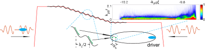
We propose to generate a microbunched high quality electron beam by superimposing a small amplitude sinusoidal density modulation on the ramp so that the density in the ramp is, where is the length of the ramp, and are the amplitude and wavenumber of the modulation. The modulation only has to be on the electrons, but it can also be on the ions as well. Substituting the expression for the modulated ramp into the equation for the phase velocity of the wake gives where is the position inside the wake and is the normalized density gradient of the ramp. This shows that when , the phase velocity can oscillate between subluminal () and superluminal () so that injection can be turned on () and off () in the ramp. More details are provided in the supplement. After injection, the electrons are mapped to the tail of the wake sequentially, i.e., the electrons injected earlier sit in front of the electrons injected later (Fig. 1) due to the gradual elongation of the bubble in the downramp. Thus, the duration of the electrons can also be compressed significantly depending on the rate of the elongation, and the period of the charge distribution can be shrunk by several orders of magnitude, i.e., from optical frequency to X-ray frequency (Fig. 1). This bunched beam has similar properties as a beam from normal density downramp injection Xu et al. (2017), i.e., it has high current, low emittance and low energy spread; thus it may be used to produce fully coherent, stable, hundreds of gigawatt X-rays with femtosecond duration in a short resonant undulator.
Such electron density modulations can be realized through the ponderomotive force of two counter-propagating linearly polarized laser pulses of the same frequency. The modulation will be at half the wavelength of lasers so injection will turn on and off with a length scale of half the optical wavelength. As illustrated in Fig. 1, two non-relativistic lasers ( where is the vector potential of the laser) with identical frequencies propagate into the plasma from both ends and interfere inside the density ramp. This results in an electron density modulation (black line in Fig. 1) with an amplitude determined through the balance of the ponderomotive force on the electrons with the charge separation force between the electrons and ions.
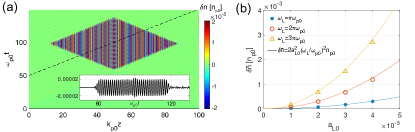
The amplitude of the density modulation can be estimated from where is assumed. If the envelop of the lasers rises slowly compared with the plasma oscillation, follows the envelope of . For the lasers with an approximately trapezoid shape, the perturbed density saturates at sup . 1D particle-in-cell (PIC) simulations are conducted to confirm the creation of this density modulation. A cold plasma with constant density is distributed between and and two lasers pulses with propagate towards one another from the two ends of the plasma. The plasma electron density perturbation is shown in Fig. 2(a) where a spatial sinusoidal density modulation is present in a rhombic region of the space. The inset shows the density seen by an observer moving at at a later time where the dashed line is its trajectory. The plasma density is modulated at wavenumber and its amplitude is . The frequency and intensity of the colliding lasers are scanned, and the amplitudes of the excited density modulation are summarized in Fig. 2(b). Good agreement between the simulations and the formula are obtained.
To demonstrate the bunched beam generation, we use the quasi-3D version Davidson et al. (2015) of the fully relativistic PIC OSIRIS Fonseca et al. (2002). The and modes (physical quantities are of the form , where is the azimuthal angle in the transverse plane) are included to model the linearly polarized lasers. A fixed simulation box with dimensions of and with grids along the and directions, respectively. This corresponds to a grid size along the of which is needed to resolve the short scales of the injected and trapped electrons. Each cell contains 8 macro-particles to represent the beam driver and the plasma electrons respectively. A Maxwell solver which can model relativistic particles with high fidelity is used Xu et al. (2020). As illustrated in Fig. 1(a), a plasma starts from with a density that drops linearly to from to and extends to with . The normalized density gradient of this ramp is . Two laser pulses, polarized along with and are sent from both ends of the plasma and propagate toward one another. The lasers have the same longitudinal profile as shown in Fig. 2, and a Gaussian transverse profile with a spot size at focus and a focal plane of . A plasma density modulation with wavelength is observed around the ramp region as shown in Fig. 3(a). The black line shows the modulation amplitude at which varies along the transverse directions due to the Gaussian transverse distribution of the lasers. The blowout radius of the wake is , so the modulations are relatively constant in the region of physical interest.
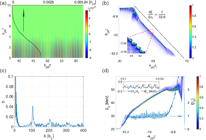
The electron beam driver has an energy of , a peak current of , a spot size of , and a duration of . Plasma electrons are completely expelled by the electric field of the driver and some of them are pulled back toward the axis by the immobile ions and form a high-density sheath Lu et al. (2006). When propagating through a region of decreasing density, the wake expands, and some sheath electrons are injected at the tail end of the wake. These electrons are longitudinally locked with the driver since they are both highly relativistic. We track these injected electrons and show their initial positions and their relative positions inside the wake after injection in Fig. 3(b). It is obvious that the injection position is modulated at the plasma density modulation wavelength () as shown in the enlarged inset. There is a mapping between the initial and final position of an electron after injection Xu et al. (2017), i.e., where the wake wavelength observed from simulations is used. Thus, the macro length and micro modulation period are compressed by a factor of for . A black line with is shown for reference. Taking into account that , the harmonic number, defined as the ratio of the colliding laser period and the density modulation period of the injected electrons, is , i.e., for . We note there is also some discrete injection before and near the end of the ramp, however the electrons injected from these regions are not bunched, as evidenced by constant value of even though is changing, due to the lack of the above linear mapping which is only present in the ramp.
A bunching factor is usually used to quantify the modulation, where is the total number of the electrons. As shown in Fig. 3(c), the bunching factor of the injected beam reaches its maximum at with and the second (third) harmonic appears at with . We note that only electrons with are used to calculate the bunching factor.
The longitudinal phase space of the injected electrons and its current profile at are shown in Fig. 3(d), where the bunched structure is seen clearly. The beam has a positive energy chirp () since the electrons at the head are injected at earlier times and are thus accelerated over a longer distance Xu et al. (2017). A sinusoidal energy modulation with an amplitude is present in the longitudinal phase space. This is caused by the axial space-charge interactions between the bunched electrons while they are at low energies because the axial electric field of relativistically moving electrons decreases rapidly with their energy (). The chirp-corrected average energy modulation and the current profile of the beam are shown in the inset of Fig. 3(d). We can see the energy modulation is approximately ahead of the currents (density) modulation in phase which confirms that the space charge forces from the current modulation are the cause of the sinusoidal energy modulation. The degradation of the bunched structure induced by this energy modulation when the beam is boosted to higher energy is negligible. The slippage induced by the energy modulation is , which is much less than the bunching wavelength when and are substituted into the formula.
This beam is characterized by a slice energy spread of , an average current of , and a normalized emittance of , which is suitable to drive an XFEL. However, there is a large energy chirp [] formed during the injection process. However, this chirp can be mitigated by an inverse chirp naturally imposed by the acceleration gradient inside the wake Lu et al. (2006) (electrons injected first reside farther forward in the wake where the acceleration gradient is smaller). Thus, there is an optimized acceleration distance where the beam achieves a flatter longitudinal phase space Xu et al. (2017) that minimizes the projected energy spread of the macrobunch.
In order to understand how to choose plasmas parameters to optimize the process, we performed a wide parameter scan using quasi-3D OSIRIS with only the mode where a density modulation with is initialized on top of a plasma downramp. Since we are not including self-consistently lasers to create the modulation, we use a moving window with dimensions . More details for the parameters of the simulations can be found in the supplement. To isolate the physics, we also employ a non-evolving beam driver to model the injection and acceleration. The dependence of the harmonic number on the gradient of the ramp is shown in Fig. 4(a) (where the theory curve is also plotted). Clearly only depends on the gradient of the ramp , not on the modulation period. When using a ramp with , the modulation frequency of the injected electrons is as high as 900 times of the laser frequency, i.e., , which is one order of magnitude higher than the number from staged HGHG ( Allaria et al. (2013)) and EEHG ( Ribič et al. (2019)). Normalized units are used in the above results where the modulation frequency is scaled to the plasma frequency. We can choose a normalized density to make connections with possible near-term experiments. Fig. 4(b) shows the bunching wavelength vs g for various for (assuming that the density wavelength is half ) and it can be seen that modulations at several nm are achieved. In principle, beams with shorter modulated wavelength can be injected if the ramp density gradient is smaller or the density modulation wavelength of the ramp is shorter, which might be the case for shorter wavelength lasers. The predicted results when is shown in black line in Fig. 4(b) where 0.23 nm bunching wavelength is achieved when .
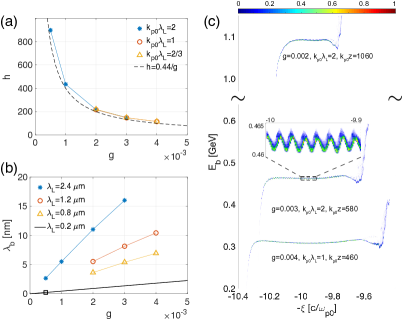
In Fig. 4(c), we show that that when the injected electrons are accelerated to an optimized distance Xu et al. (2017) the projected energy spread of the beam core is less than 1 . Since the initial energy chirp induced during the injection process is inversely proportional to the gradient of the ramp, i.e., , a long acceleration distance is required to remove it if is small. This will also lead to a higher energy beam. Beam loading Tzoufras et al. (2008) which is included in the simulations can also play a role during the removal of the chirp.
As noted above the longitudinal space charge can create a sinusoidal energy modulation along the beam as shown in the inset of Fig. 4(c). By letting the beam go through a chicane where the electrons’ axial location changes according to their energy, this energy modulation can be utilized to enhance the bunching factor at the and their harmonics as in a HGHG Yu (1991). For example, a small chicane with can increase the bunching factor of the beam from at the fundamental frequency from to and at the third harmonic from to .
In order to transport the beams out of the plasma into an undulator without emittance degradation a plasma matching section with gradually varying density is needed Floettmann (2014); Dornmair et al. (2015); Xu et al. (2016b) to match the beam. The matched beam can then travel through a resonant undulator to generate fully coherent radiation. Due to the high current () and low emittance ( ) of these beams, hundreds of GW of radiation can be emitted in a short beam-undulator interaction distance. Taking the 1.09 GeV injected beam from case as an example exp , 3.6 , fully coherent radiation with a stable power of TW could be emitted from a meter long resonant undulator with Xie (1995).
In conclusion, we have proposed a novel approach that uses a PWFA and density modulated downramp to produce ultra-bright and high-quality electron bunches with a current modulation at X-ray wavelengths. We have presented fully self-consistent PIC simulations that show that the ponderomotive force of two counter propagating lasers that overlap in the downramp can produce a sufficient density modulation with a wavelength half of the laser wavelength. The current of the injected beam is modulated at a wavelength times smaller than the modulation wavelength in the downramp.
Acknowledgements.
Work supported by the U.S. Department of Energy under contract number DE-AC02-76SF00515, No. DE-SC0010064, and SciDAC FNAL subcontract 644405, and NSF Grants Nos. 1734315 and ACI-1339893. The simulations were performed on the UCLA Hoffman 2 and Dawson 2 Clusters, and the resources of the National Energy Research Scientific Computing Center.References
- Röntgen (1896) W. C. Röntgen, Science 3, 227 (1896).
- Pellegrini et al. (2016) C. Pellegrini, A. Marinelli, and S. Reiche, Reviews of Modern Physics 88, 015006 (2016).
- Kim et al. (2017) K.-J. Kim, Z. Huang, and R. Lindberg, Synchrotron radiation and free-electron lasers (Cambridge university press, 2017).
- Yu (1991) L. H. Yu, Physical Review A 44, 5178 (1991).
- Yu and Ben-Zvi (1997) L.-H. Yu and I. Ben-Zvi, Nuclear Instruments and Methods in Physics Research Section A: Accelerators, Spectrometers, Detectors and Associated Equipment 393, 96 (1997).
- Yu et al. (2000) L.-H. Yu, M. Babzien, I. Ben-Zvi, L. DiMauro, A. Doyuran, W. Graves, E. Johnson, S. Krinsky, R. Malone, I. Pogorelsky, et al., Science 289, 932 (2000).
- Allaria et al. (2012) E. Allaria, R. Appio, L. Badano, W. Barletta, S. Bassanese, S. Biedron, A. Borga, E. Busetto, D. Castronovo, P. Cinquegrana, et al., Nature Photonics 6, 699 (2012).
- Allaria et al. (2013) E. Allaria, D. Castronovo, P. Cinquegrana, P. Craievich, M. Dal Forno, M. Danailov, G. D’Auria, A. Demidovich, G. De Ninno, S. Di Mitri, et al., Nature Photonics 7, 913 (2013).
- Stupakov (2009) G. Stupakov, Physical review letters 102, 074801 (2009).
- Xiang and Stupakov (2009) D. Xiang and G. Stupakov, Physical Review Special Topics-Accelerators and Beams 12, 030702 (2009).
- Xiang et al. (2010) D. Xiang, E. Colby, M. Dunning, S. Gilevich, C. Hast, K. Jobe, D. McCormick, J. Nelson, T. Raubenheimer, K. Soong, et al., Physical review letters 105, 114801 (2010).
- Zhao et al. (2012) Z. Zhao, D. Wang, J. Chen, Z. Chen, H. Deng, J. Ding, C. Feng, Q. Gu, M. Huang, T. Lan, et al., Nature Photonics 6, 360 (2012).
- Xiang et al. (2012) D. Xiang, E. Colby, M. Dunning, S. Gilevich, C. Hast, K. Jobe, D. McCormick, J. Nelson, T. Raubenheimer, K. Soong, et al., Physical review letters 108, 024802 (2012).
- Hemsing et al. (2016) E. Hemsing, M. Dunning, B. Garcia, C. Hast, T. Raubenheimer, G. Stupakov, and D. Xiang, Nature Photonics 10, 512 (2016).
- Ribič et al. (2019) P. R. Ribič, A. Abrami, L. Badano, M. Bossi, H.-H. Braun, N. Bruchon, F. Capotondi, D. Castronovo, M. Cautero, P. Cinquegrana, et al., Nature Photonics 13, 555 (2019).
- Tajima and Dawson (1979) T. Tajima and J. M. Dawson, Phys. Rev. Lett. 43, 267 (1979).
- Chen et al. (1985) P. Chen, J. Dawson, R. W. Huff, and T. Katsouleas, Physical review letters 54, 693 (1985).
- Joshi (2006) C. Joshi, Scientific American 294, 40 (2006).
- Blumenfeld et al. (2007) I. Blumenfeld et al., Nature 445, 741 (2007).
- Litos et al. (2014) M. Litos, E. Adli, W. An, C. Clarke, C. Clayton, S. Corde, J. Delahaye, R. England, A. Fisher, J. Frederico, et al., Nature 515, 92 (2014).
- Gonsalves et al. (2019) A. J. Gonsalves, K. Nakamura, J. Daniels, C. Benedetti, C. Pieronek, T. C. H. de Raadt, S. Steinke, J. H. Bin, S. S. Bulanov, J. van Tilborg, et al., Phys. Rev. Lett. 122, 084801 (2019), URL https://link.aps.org/doi/10.1103/PhysRevLett.122.084801.
- Adli et al. (2018) E. Adli, A. Ahuja, O. Apsimon, R. Apsimon, A.-M. Bachmann, D. Barrientos, F. Batsch, J. Bauche, V. B. Olsen, M. Bernardini, et al., Nature 561, 363 (2018).
- Xu et al. (2017) X. Xu, F. Li, W. An, T. Dalichaouch, P. Yu, W. Lu, C. Joshi, and W. Mori, Physical Review Accelerators and Beams 20, 111303 (2017).
- Dalichaouch et al. (2020) T. N. Dalichaouch, X. L. Xu, F. Li, A. Tableman, F. S. Tsung, W. An, and W. B. Mori, Phys. Rev. Accel. Beams 23, 021304 (2020), URL https://link.aps.org/doi/10.1103/PhysRevAccelBeams.23.021304.
- Lundh et al. (2013) O. Lundh, C. Rechatin, J. Lim, V. Malka, and J. Faure, Phys. Rev. Lett. 110, 065005 (2013), URL https://link.aps.org/doi/10.1103/PhysRevLett.110.065005.
- Xu et al. (2016a) X. Xu, C.-H. Pai, C. Zhang, F. Li, Y. Wan, Y. Wu, J. Hua, W. Lu, W. An, P. Yu, et al., Physical review letters 117, 034801 (2016a).
- Katsouleas (1986) T. Katsouleas, Phys. Rev. A 33, 2056 (1986), URL https://link.aps.org/doi/10.1103/PhysRevA.33.2056.
- Bulanov et al. (1998) S. Bulanov, N. Naumova, F. Pegoraro, and J. Sakai, Phys. Rev. E 58, R5257 (1998), URL https://link.aps.org/doi/10.1103/PhysRevE.58.R5257.
- Suk et al. (2001) H. Suk, N. Barov, J. B. Rosenzweig, and E. Esarey, Phys. Rev. Lett. 86, 1011 (2001), URL https://link.aps.org/doi/10.1103/PhysRevLett.86.1011.
- Geddes et al. (2008) C. G. R. Geddes et al., Phys. Rev. Lett. 100, 215004 (2008).
- Gonsalves et al. (2011) A. Gonsalves, K. Nakamura, C. Lin, D. Panasenko, S. Shiraishi, T. Sokollik, C. Benedetti, C. Schroeder, C. Geddes, J. Van Tilborg, et al., Nature Physics 7, 862 (2011).
- Buck et al. (2013) A. Buck, J. Wenz, J. Xu, K. Khrennikov, K. Schmid, M. Heigoldt, J. M. Mikhailova, M. Geissler, B. Shen, F. Krausz, et al., Phys. Rev. Lett. 110, 185006 (2013), URL https://link.aps.org/doi/10.1103/PhysRevLett.110.185006.
- (33) See more discussions in the supplement.
- Davidson et al. (2015) A. Davidson, A. Tableman, W. An, F. S. Tsung, W. Lu, J. Vieira, R. A. Fonseca, L. O. Silva, and W. B. Mori, Journal of Computational Physics 281, 1063 (2015).
- Fonseca et al. (2002) R. Fonseca et al., Lecture notes in computer science 2331, 342 (2002).
- Xu et al. (2020) X. Xu, F. Li, F. S. Tsung, T. N. Dalichaouch, W. An, H. Wen, V. K. Decyk, R. A. Fonseca, M. J. Hogan, and W. B. Mori, Journal of Computational Physics p. 109451 (2020).
- Lu et al. (2006) W. Lu, C. Huang, M. Zhou, W. B. Mori, and T. Katsouleas, Phys. Rev. Lett. 96, 165002 (2006).
- Tzoufras et al. (2008) M. Tzoufras et al., Phys. Rev. Lett. 101, 145002 (2008).
- Floettmann (2014) K. Floettmann, Phys. Rev. ST Accel. Beams 17, 054402 (2014), URL https://link.aps.org/doi/10.1103/PhysRevSTAB.17.054402.
- Dornmair et al. (2015) I. Dornmair, K. Floettmann, and A. R. Maier, Phys. Rev. ST Accel. Beams 18, 041302 (2015), URL https://link.aps.org/doi/10.1103/PhysRevSTAB.18.041302.
- Xu et al. (2016b) X. L. Xu, J. F. Hua, Y. P. Wu, C. J. Zhang, F. Li, Y. Wan, C.-H. Pai, W. Lu, W. An, P. Yu, et al., Phys. Rev. Lett. 116, 124801 (2016b).
- (42) Although the longitudinal phase space shown in Fig. 4(c) is using , we assume the beam when has a similar distribution since the fine structures of the beam affect the acceleration little.
- Xie (1995) M. Xie, in Proceedings Particle Accelerator Conference (IEEE, 1995), vol. 1, pp. 183–185.