spacing
\onlineid1042
\vgtccategoryResearch
\vgtcinsertpkg
\teaser
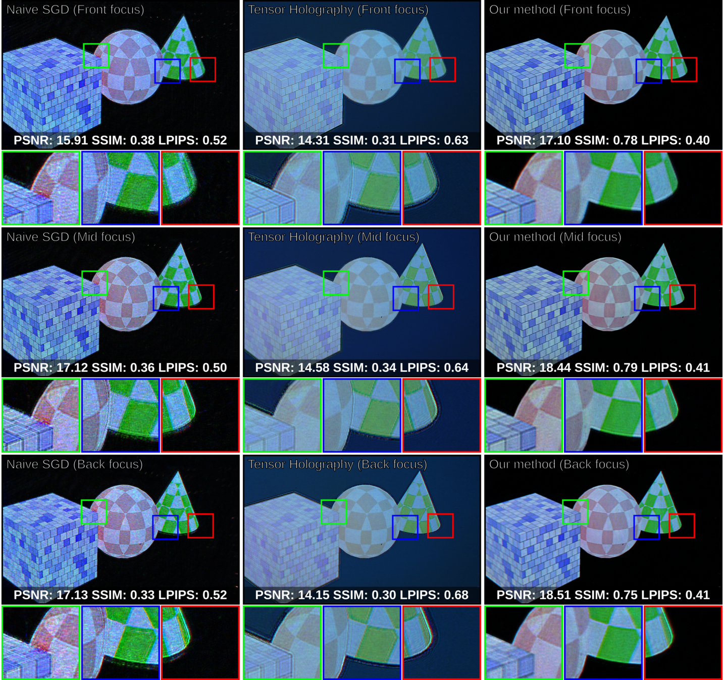
![[Uncaptioned image]](/html/2205.07030/assets/figures/teaser/teaser.png) Realistic defocus blur in multiplane Computer-Generated Holography (CGH).
We introduce a novel hologram generation pipeline for holographic displays that offer near-accurate defocus blur and mitigation of visible fringes in reconstructed images.
Here, we provide actual photographs captured from our proof-of-concept holographic display.
We capture three components of a color image using a three-color laser light source (473-515-639 nm) using the same capture exposure (20 ms) and laser powers, providing the best visual quality for each case.
We later combine three monochrome images into a full-color image in the post-process.
The state of the art method, tensor holography [31], offers sharp, high-quality images but with contrast loss.
Our proposed method mitigates these issues while offering 3D images with improved contrast, more realistic defocus blur and fringe-free images.
In this example, our approach here uses six target planes in-depth.
We produced the results for tensor holography [31] with our hardware to the best of our knowledge.
Realistic defocus blur in multiplane Computer-Generated Holography (CGH).
We introduce a novel hologram generation pipeline for holographic displays that offer near-accurate defocus blur and mitigation of visible fringes in reconstructed images.
Here, we provide actual photographs captured from our proof-of-concept holographic display.
We capture three components of a color image using a three-color laser light source (473-515-639 nm) using the same capture exposure (20 ms) and laser powers, providing the best visual quality for each case.
We later combine three monochrome images into a full-color image in the post-process.
The state of the art method, tensor holography [31], offers sharp, high-quality images but with contrast loss.
Our proposed method mitigates these issues while offering 3D images with improved contrast, more realistic defocus blur and fringe-free images.
In this example, our approach here uses six target planes in-depth.
We produced the results for tensor holography [31] with our hardware to the best of our knowledge.
Realistic Defocus Blur for Multiplane Computer-Generated Holography
Abstract
This paper introduces a new multiplane CGH computation method to reconstruct artifact-free high-quality holograms with natural-looking defocus blur. Our method introduces a new targeting scheme and a new loss function. While the targeting scheme accounts for defocused parts of the scene at each depth plane, the new loss function analyzes focused and defocused parts separately in reconstructed images. Our method support phase-only CGH calculations using various iterative (e.g., Gerchberg-Saxton, Gradient Descent) and non-iterative (e.g., Double Phase) CGH techniques. We achieve our best image quality using a modified gradient descent-based optimization recipe where we introduce a constraint inspired by the double phase method. We validate our method experimentally using our proof-of-concept holographic display, comparing various algorithms, including multi-depth scenes with sparse and dense contents.
HardwareEmerging TechnologiesEmerging optical and photonic technology; \CCScatTwelveHardwareCommunication hardware, interfaces and storageDisplay and imagers
Introduction
Real-time computer-generated visuals are confined chiefly to flat images. Rendering realistic-looking perspectives of a scene on a flat two-dimensional screen is possible today. Nevertheless, the actual illusion of perceiving 3D scenes that match our experiences in real life is still beyond today’s computer graphics and displays. There is a growing consensus in the industry and academia that Computer-Generated Holography (CGH) [32] methods can help address these issues, and holography can stand out as the next-generation display technology [23]. The goal of CGH research is to provide computer-generated 3D visuals indistinguishable from real life by the human visual system.
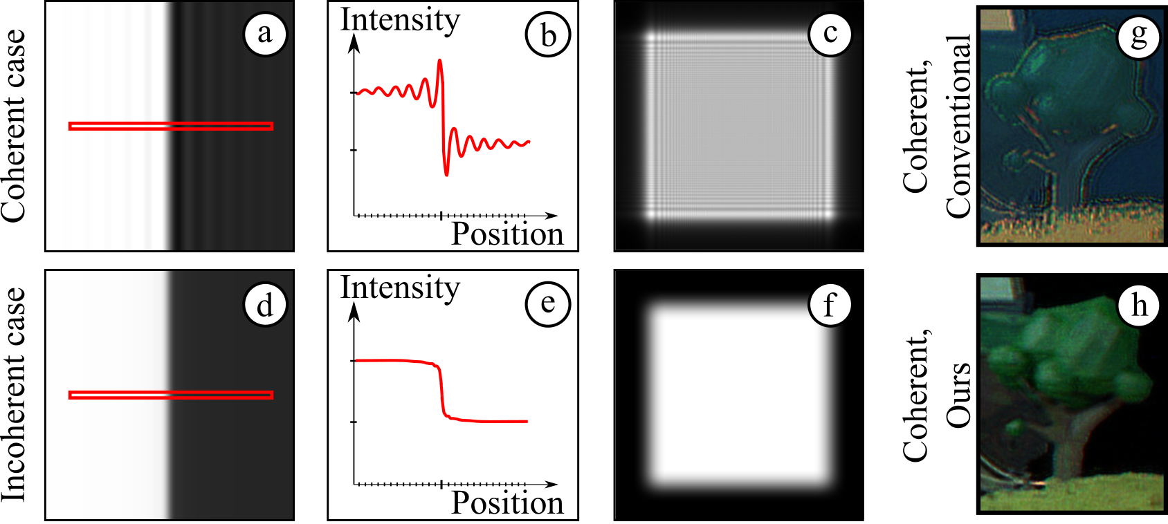
With the advent of machine learning techniques and accelerated computing capabilities, the image quality of visuals generated by CGH has improved tremendously, specifically for 3D case [31]. However, there are still barriers to achieving realistic visuals with CGH, specifically in the defocused parts of a scene. As CGH typically relies on coherent light sources, it makes defocused parts of a scene look unfamiliar to a human observer. Born and Wolf [4] describe this apparent difference between coherent and incoherent defocus blur as the edge fringe issue in 3D holography (see Figure 1).
In this work, we address the difference between coherent and incoherent blur in the context of multiplane CGH. We argue that an improved targeting scheme and a new loss function that accounts for these differences can help reproduce incoherent defocus blur in CGH when reconstructing multiplanar images using coherent light sources. We show that such a loss function and a targeting scheme work with the most common CGH calculation methods, including Gerchberg-Saxton (GS) [41], Stochastic Gradient Descent (SGD) [38] and Double Phase (DP) [13] based approaches. We build a proof-of-concept holographic display to validate our method experimentally. Our primary technical contributions include the following:
-
•
Loss function and targeting scheme. We introduce a new loss function that evaluates focused and defocused parts of target images in multiplane CGH. We also present a new targeting scheme to set proper target images, including defocused parts for multiplane image reconstructions. Our loss function and targeting scheme can generate near-accurate defocus blur approximating incoherent cases using coherent light.
-
•
Multiplane hologram generation pipeline. Our loss function and targeting scheme are compatible with various optimization and learning methods. We describe our hologram generation pipeline for reconstructing multiplane images on an SLM plane (0 cm away) or a near field plane (15 cm away). Our hologram generation pipeline uses a custom optimization recipe that combines double phase constraints with SGD optimizations.
-
•
Bench-top holographic display prototype. We implement a proof-of-concept holographic display prototype using three lasers, and a phase-only Spatial Light Modulator (SLM) augmented with various optical and optomechanical parts. This prototype serves as a base for validating our algorithms for our method.
1 Related Work
We introduce a new targeting scheme and a loss function to improve the visual quality of image reconstructions simultaneously at multiple planes – not varifocal CGH [35]. Notably, our work deals with the edge fringe issues and differences in defocus blur between incoherent and coherent light in holographic displays. Here, we provide a brief survey of prior art in relevant CGH methods.
1.1 Holographic Displays
A holographic display [32] aims to produce genuine 3D light fields [21] using the optical phenomena of diffraction and interference in coherent imaging [4]. Typically, in these holographic displays, an SLM represents these diffraction and interference patterns in a programmable fashion. While holographic displays can come in different types, such as near-eye displays [5], desktop displays [19], and even contact lens displays [29], all these displays claim to offer near-correct optical focus cues [37]. However, the defocused parts represented in these displays do not look natural due to the algorithmic approaches used (see Figure 1).
In our work, to demonstrate our approach, we build a holographic display prototype following the guidance from the recent literature [31]. Though the general layout of our display is similar to the standard phase-only holographic displays, the more critical details of our implementation are unique to its case as discussed in Section 4.
1.2 Computer-generated Holography
CGH deals with computing a hologram that generates the desired light distribution over a target plane when displayed on an SLM [32]. Hologram calculation with CGH is known to be computationally expensive due to the complexity of physical light simulation models used in CGH [40, 39]. The recent advancements in GPUs and deep learning spark the development of new algorithms that promise hologram generation at interactive rates in the future [31]. Conventional CGH algorithms can be broadly classified using their scene representations. Such scene representations include point-cloud [33], ray [34], polygon [26], light field [30], and multiplane [25] representations. We suggest our readers consult the survey by Cordaet al. [10] for a complete review of conventional CGH algorithms.
We employ a multiplane representation approach for 3D image reconstructions. Our work differs from the rest of the literature [25, 11, 15, 31, 28, 9] in the novel targeting scheme and loss function for the multiplane optimization, which mitigates edge fringe issues and helps reconstruct realistic defocus blur. Although the work by Choiet al. [8] generates realistic defocus using a DMD time-multiplexed SLM, to our knowledge, our work differs as our work targets common liquid-crystal based SLMs. Thus, we believe our work is the first in addressing edge-fringe issues without relying on time-multiplexing. Our work also differs in calculating phase-only holograms as we show that it can operate with various kinds of CGH methods, including GS [41], SGD [38] and DP [13] based approaches.
2 Targeting Scheme and Loss Function for Multiplane Computer-Generated Holography
We aim to calculate phase-only holograms that simultaneously reconstruct high-quality images at multiple planes at various depth levels. Here high-quality refers to the generation of multiplane images free from edge fringes with accurate defocus blur.
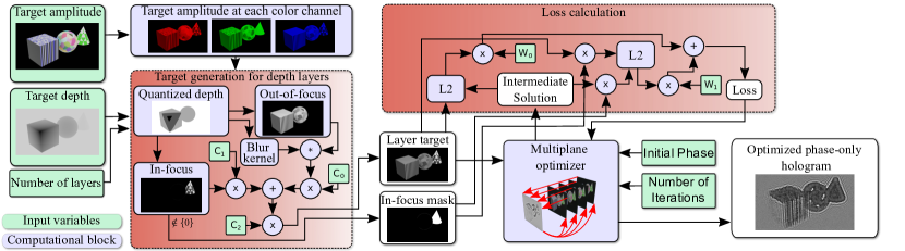
When a homogeneous, collimated, coherent light source (e.g., a laser) illuminates a phase-only hologram, light diffracts from that phase-only hologram. Diffracted light interferes and forms the intended images at the target planes in front of the hologram. To successfully achieve our goals, we must fulfil two primary objectives. Firstly, we have to identify the target images for each plane at different depth levels. Secondly, we must identify a loss function to evaluate our reconstructions at each plane in depth. Fig. 2 provides an overview of our targeting scheme and our loss function.
2.1 Targetting scheme
A typical multiplane image reconstruction method for CGH requires representing a 3D scene with a target amplitude image, and a target depth, . In a naïve approach [28], layer targets, , are composed of cropped parts of a target amplitude image from each pixel depth level. Hence, layer targets at each layer, , is a sparse image filled with black pixels surrounding in-focus pixels. In other words, a conventional optimizer for CGH would force the image reconstruction solution to provide black pixels at places where defocus blur of other objects should appear in reality. Specifically, when the target depth planes are packed closely in terms of distances (a few millimeters), coherent image blur dominates the naïve approach’s solution, leading to noisy reconstructions suffering from visual quality issues. The recent and common literature that uses optimization [36] and machine learning methods [18] widely adopts the naïve approach. Forcing the image reconstruction to provide black pixels instead of natural defocus at defocused regions causes edge-fringe artifacts to appear in the final image as can be observed in the previous literature [11, 15, 31, 28, 9]. Specifically, edge-fringe artifacts become more pronounced across occlusions in a given scene as these parts are also forced to be painted with black rather than the defocused version of the part of a target scene. Hence, we argue that multiplane image reconstruction is beyond resolving an optimization or a learning problem, and it has to also deal with the problem formulation. We argue that tailoring target images can help improve multiplane image reconstructions in CGH.
Inspired by Depth-of-Field (DoF) rendering [20] in conventional 2D computer graphics, we introduce a new targeting scheme for identifying target images at each plane in depth. Commonly, a comes with an eight-bit pixel depth. Firstly, we quantize a given . In a typical quantization step from our method, we quantize to a pixel depth between one to four bits (at most 16 consecutive planes). Our choice in the number of planes emerges from an earlier analysis [2], in which RGBD natural image datasets are analyzed by taking into account the human visual system’s DoF. Quantized depth images help us identify regions from as in-focus regions, , and out of focus, , at each depth level, . We convolve regions of with a Gaussian kernel to achieve a defocus similar to an incoherent case, . Here, the Gaussian kernel’s size is in inverse relation with the distance to the focus plane. We sum and using weights, leading to the final target form,
| (1) |
where is the target image at k-th plane, and represents weights. These weights help us control brightness levels of sharp parts, blurry parts and overall image. To our knowledge, in multiplane CGH, our targeting scheme is the first to add defocus-blur to target images.
2.2 Loss Function
Evaluating multiplane image reconstructions requires a loss function. Evaluating the image quality of the reconstructed images often involves measuring L2 distance between each element of layer targets, and reconstructed images . We argue that a multiplane image reconstruction problem demands a more sophisticated image quality metric. Our argument originates from the fact that different parts of the image will come into focus at each depth level while the remaining parts have to be blurry. Hence, we argue that in-focus regions require more attention in precision than out-of-focus parts. Thus, we propose a new loss function, , a weighted sum of two different loss functions,
| (2) |
where represents weights, represents a reconstructed image at a kth plane, and represents a binary mask highlighting only the sharp parts in a kth plane. We survey various values of and in a brute-force fashion. In our practical observations, choosing leads to the best looking visuals in our holographic display. Weighted with , part of is a standard L2 norm that evaluates the entire image with respect to a target image. The part of evaluates the in-focus part of an image with respect to a target image (L2-focus). For accounting gaze-contingency in this loss, see our supplementary materials.
3 Calculating Multiplane Holograms
The required ingredients for calculating phase-only holograms are all introduced at this point, including our targeting scheme, our loss function and a model for propagating light (see our supplementary materials). The routines discussed here are valid for a phase-only hologram, , illuminated by a coherent beam, .
We will deal with reconstructing 3D images in the whereabouts of an SLM, leading to light propagation distances, , from to a few millimetres. Commonly, in this regime, people use DP [13] method to encode a complex field into a phase-only hologram (see Maimoneet al. [24] for a simplified formulation). Across the literature [24, 31], images reconstructed at this regime provide the best known visual quality. We can use our targeting scheme with the Double Phase method. In that case, we couple each layer target, , with a random phase to generate a target field. Then, we propagate each target field from its plane ( in our simulations) to a phase-only hologram plane. We sum up all the propagated fields from each target at the hologram plane. Finally, we follow the same routine from recent works [24, 31] by shifting the field towards SLM plane () and applying DP encoding. However, combining the DP with our targeting scheme would not entirely resolve the raised issues in holographic displays. We provide actual evidence in our evaluation section accordingly.
Alternatively, in this regime, a typical optimization method would have to first optimize a hologram for some propagation distance, then rely on shifting and DP coding. We ask ourselves if a hologram could be directly optimized on the SLM plane. Given that the propagation distance is small, the conventional beam propagation methods [12] would not hold well or provide a meaningful result at near zero distance. We find out that if we propagate a phase-only hologram from an SLM plane some distance (e.g., ) and propagate it back to the hologram plane (e.g., ), we can reconstruct an image on an SLM plane, leading to a formulation,
| (3) |
where and represent light transport and represents the reconstructed image. The composition of these propagations would be the identity since propagation is inverted by backpropagation. However, in this case, the wavefront at the SLM can be optimized because the wavefront at a distance r must be cropped to a region that does not include the full wavefront of that plane. Physically, this would correspond to having an aperture at a distance after the SLM. Using this forward model, we optimize a phase-only hologram using SGD implementations from recent literature [6, 28]. Our findings suggest that this approach would lead to noisy image reconstructions. We fix this noise issue by constraining the phase updates of SGD, of , with an approach inspired from the DP method. Our phase values, , follows,
| (4) |
where offset is a variable to be optimized.
Since there is a readily available differentiable version of beam propagation [3] compatible with widely used machine learning libraries [27], optimizing phase-only holograms becomes even an easier task. We provide a pseudo-code for our SGD optimization routine as in Listings 1.
4 Holographic Display Prototype
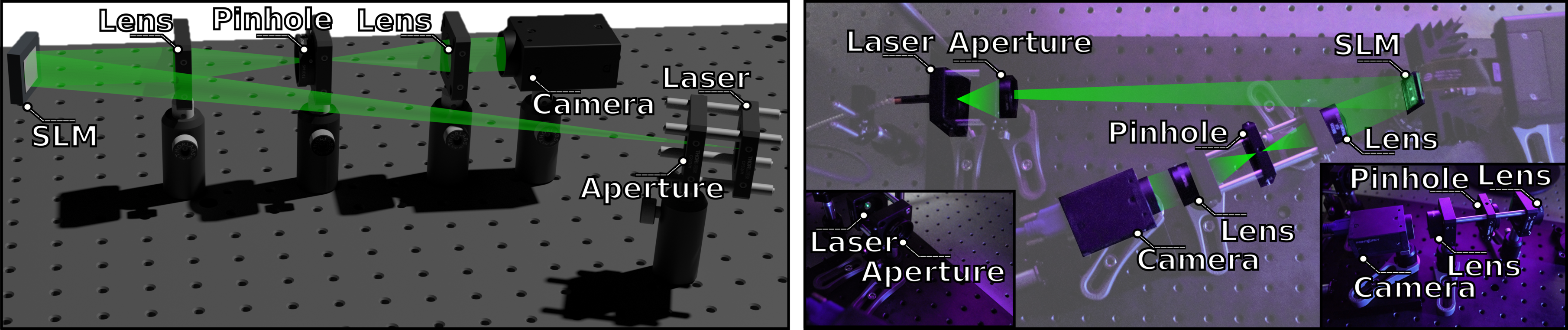
To demonstrate that we can leverage our CGH approaches in practice, we build a proof-of-concept holographic display prototype using off-the-shelf components. We provide a detailed overview of our optical schematic and photographs from our experiment bench in Fig. 3.
Optical and Optomechanical Assembly.
The optical path of our prototype starts from a single-mode fiber-coupled multi-wavelength laser light source, LASOS MCS4, which combines three separate laser light sources peeking at 473 nm, 515 nm and 639 nm. We limit the diverging beams coming out of our fiber with a pinhole aperture, Thorlabs SM1D12. After this pinhole aperture, light beams reach our phase-only SLM, Holoeye Pluto-VIS. The phase-modulated beam arrives at a 4f imaging system composed of two 50 mm focal length achromatic doublet lenses, Thorlabs AC254-050-A, and a pinhole aperture, Thorlabs SM1D12, removing undiffracted light. We capture the image reconstructions with an image sensor, Point Grey GS3-U3-23S6M-C USB 3.0, located on an X-stage (Thorlabs PT1/M travel range: 0-25 mm, precision: 0.01 mm).
Our holographic display prototype is configured as an off-axis imaging system. We are using the half diffraction order location for our optical reconstructions. Our desired half diffraction order beam is on-axis with respect to the 4f imaging system, and the illumination beam is slightly off-axis. We rely on a linear grating term which will be explained in the Computation and Control Modules paragraph. Therefore, a beamsplitter in front of SLM and a linear polariser are not required for our prototype.
Computation and Control Modules.
We use a computer with NVIDIA GeForce RTX 3070 laptop GPU with 8 GB memory and an Intel i7, 4.6 GHz CPU to drive our holographic display prototype. To avoid undiffracted light, we update calculated with a linear phase grating term,
| (5) |
where , , represents the original phase of .
5 Evaluation
In all our experiments, we use the exact exposure times, , and distances between our target planes set to . For example, if we use four planes, the reconstructed images will correspond to a volume with (). For more results, please to consult our supplementary materials.
Defocus blur
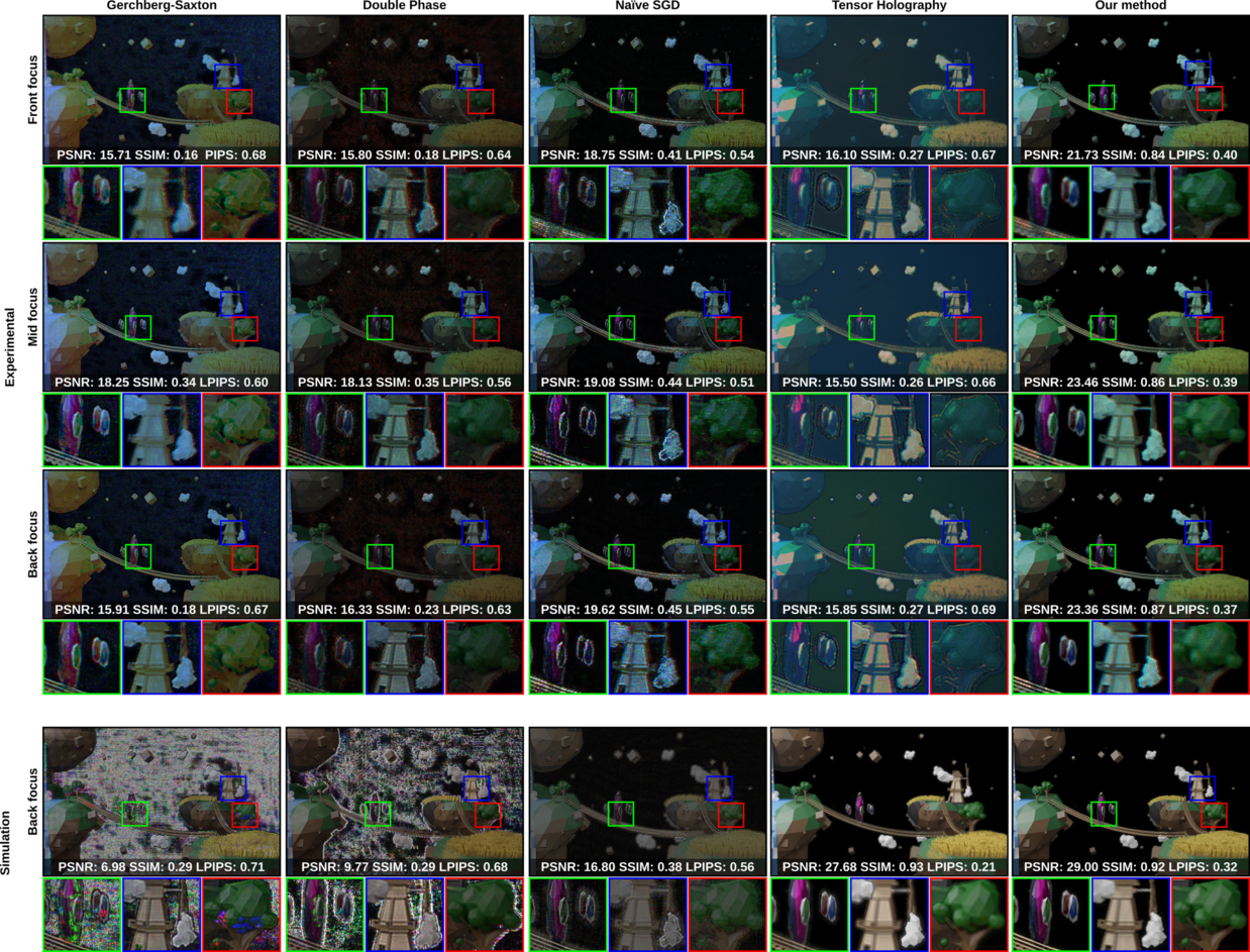
A sample experimental and simulation comparison is provided as in Figure 4. The naïve multiplane targeting approach, where defocus parts are painted with black pixels in the target image, forms a baseline for our comparison. When GS and DP are used with näive multiplane targeting, they lead to poor image quality. However, naïve multiplane targeting with SGD [6, 28] provided a result with more reasonable image quality. Thus, we discard GS and DP with naïve targeting from our discussion. Instead, we use GS and DP methods with our targeting schemes. Although these options with our targeting lead to a more reasonable visual quality, it is still lacking compared with state of the art. Finally, we also add the tensor holography [31] to our comparison. Our experimental results showed that our method using SGD optimizations with a DP inspired phase update rule provided the most appealing image quality with realistic looking defocus blur. Our experimental findings are in line with our simulation results in our assessment. The simulation case for tensor holography has the contour outlines in defocus regions but not pronounced as in the experimental result from our evaluation and the original work.
Edge fringe
The edge fringe issue in CGH is typically highly apparent in contents dominated by black pixels, making such content an excellent way to quantify our improvement over existing literature. In Figure 5, we compare our method against the state of the art while targeting sparse content dominated by black pixels. Our method distinguishes itself as an edge fringe artifact free result.
Blur size and number of depth planes.
Our multiplane CGH generation pipeline can generate images with various multiple quantization levels in depth. In addition, our CGH pipeline offers control over blur size, potentially leading to rendering scenes in a styled way according to a viewer’s taste. In our method, Gaussian Kernels can be replaced with Zernike polynomials in the future to support the prescription of a viewer. We provide the evidence that our CGH pipeline can provide images with various quantizations and blur sizes as in our supplementary materials.
Required computational resources.
For our method, optimizing a full color hologram for a scene with eight target planes takes 57 seconds with a memory footprint of 4623 MB using NVIDIA GeForce RTX 3070 laptop GPU with 8 GB memory. In comparison, our baseline with naive targeting takes 55 seconds to run while requiring 4587 MB on the same GPU. It should be noted that tensor-holography [31] is significantly faster than optimization methods as it replaces the iterative optimizations with a network. For our case it takes almost 1.5 second to generate a full color hologram and requires 5908 MB of memory.
Projection distances.
The standard literature in the previous ten years mainly relied on generating images away from an SLM, either inside or in front of it (e.g., [28, 16]). Specifically, augmented reality near-eye display designs that place SLMs in front of an eye [16] could benefit from improved CGH methods that work better in long projection distance cases as these displays generate images inside an SLM. Typically, the edge fringe artifacts become more apparent, and image quality gets worse when images are reconstructed away from an SLM. These issues make the long projection distance case a perfect base for analyzing the quality of CGH methods. In our pipeline, if we update our forward model in Equation 3 by dropping the back projection part, leading to , and if we drop our phase update rule in Equation 4, we can use our multiplane CGH pipeline for long projection distances. In our supplementary, we provide an evidence that our method improves image quality also in long projection distances. We provide an evidence for compatibility to AR near-eye display, our readers can consult to our supplementary material for this evidence.
Using our proof-of-concept holographic display, we demonstrated a complete multiplane CGH calculation pipeline with near-accurate defocus blur. While we noticeably mitigate edge fringe issues and our results approximate natural focus blur, there are remaining issues and potential new research paths. These issues and research paths includes occlusion in multiplanar holography, perceptual holography and practical issues. We expand on these topics with a discussion included in our summplementary.
6 Discussion
We demonstrated a new CGH method that introduces a novel loss function, targeting scheme, and optimization method for multiplane image reconstructions. In addition, we also built a proof-of-concept holographic display to assess the experimental performance of our introduced algorithmic methods. While we noticeably mitigate edge fringe effects and our results approximate natural focus blur, there are remaining issues and potential new research paths that can help us converge to better implementations in the future.
Perceptual Holography.
Recent literature [35, 7, 5] promises to take advantage from the qualities of human visual system by introducing new loss functions that help reconstruct images at peripheral vision with perceptual guidance and gaze-contingency. Although these works open up a new combination in research, these works can be best described as first stabs at achieving true perceptual realism. Future perceptual graphics and computational displays research must find ways to carefully tune the image spatiotemporal qualities of holography to achieve life-like visuals.
Occlusion in multiplanar holography.
A change in a user’s point-of-view when observing multiplane images can lead to occlusion related issues with most multiplane CGH approaches, including ours. These occlusions manifest as missing image parts or images that look “holo” (seeing one object inside another). Hence, addressing the occlusion issue is essential and an outstanding scientific question in multiplane CGH. Further research in data representations in multiplane is also required to provide occlusions similar to point-based representations in the literature [31].
Visual quality metrics.
We strongly argue that commonly used image quality assessment metrics such as PSNR and SSIM do not apply to multiplane holograms for various obvious reasons. For instance, there is no metric to assess the defocus blur in 3D scenes. The values coming out of such metrics do not entirely correlate with the experience of a human subject (e.g., marking blurry as better to sharper images with speckle noise). The community can benefit from a new set of metrics tailored for 3D CGH.
Learned Holography.
Learning methods have garnered interest among the CGH community. An exciting line of research from work by Leeet al. [22] promises to benefit Variational Autoencoders (VAE) for generating complex holograms. Though their work targets lower resolution image reconstructions on a single plane, VAEs may promise a dimensionality reduction in our problem (smaller network). On the other hand, there is active research on replacing optimization steps and further enhancing optimization routines with learned-references [14]. Optimizer based solutions (e.g., SGD) can provide much higher quality holograms concerning end-to-end hologram generation networks. Accelerating the optimizations with unrolled networks rather than deriving an end-to-end solution for hologram generation can also provide a gateway towards higher quality image reconstructions that also arrive with the benefit of speed. For us, improving optimization routines with networks stands out as an exciting opportunity.
Practical issues
Despite the well-known advantages of CGHs, there are still many challenges to be addressed, including field-of-view [17], depth-of-field [25], and speckle noise [32]. Another challenge in working with a laser-based display system is dust and imperfections on optical components such as diamond turning marks, which causes diffraction problems and undesired fringe patterns on the holograms. We believe holographic displays need to support imperfect optical components to be practical and highly reproducible at the consumer level. These practical issues may have seen as engineering hurdles, but we believe these issues fall into the category of tolerance related research in optical and algorithmic designs.
7 Conclusion
The display and graphics technologies industry is, in many ways, well established, yet the future remains unsettled. Innovations leading to seamless blends of graphically created digital 3D objects with the physical natural world will disrupt the status quo.
To fulfil the demands of this ultimate goal, we evaluate CGH as the future display and graphics technology. Specifically, we study representing 3D scenes as multiplane images using CGH without the inherent coherent artifacts such as fringes or incorrect defocus blur. Our approach provides a phase-only hologram that can simultaneously reconstruct images at various depths with the near-correct optical focus cues. While we offer a unique solution to some of the fundamental challenges of coherent display systems, hurdles remain in CGH implementations to claim superiority over other display and graphics technologies. We hope to inspire the relevant research communities to investigate CGH as the ultimate display and graphics method.
Supplementary material
The code base of our framework is available at our repository [1]. We provide the source files of our figures in our supplementary documentation.
Acknowledgement
The authors would like to thank reviewers for their valuable feedback. We would like to thank Erdem Ulusoy and Güneş Aydındoğan discussions in the early phases of the project; Tim Weyrich and Makoto Yamada for dedicating GPU resources in various experimentation phases; David Walton for their feedback on the manuscript; Yuta Itoh is supported by the JST FOREST Program Grant Number JPMJPR17J2 and JSPS KAKENHI Grant Number JP20H05958 and JP21K19788. Hakan Urey is supported by the European Innovation Council’s HORIZON-EIC-2021-TRANSITION-CHALLENGES program Grant Number 101057672 and Tübitak’s 2247-A National Lead Researchers Program, Project Number 120C145.. Kaan Akşit is supported by the Royal Society’s RGS\R2\212229 - Research Grants 2021 Round 2 in building the hardware prototype.
References
- [1] K. Akşit. Realistic defocus, May 2022.
- [2] K. Akşit, P. Chakravarthula, K. Rathinavel, Y. Jeong, R. Albert, H. Fuchs, and D. Luebke. Manufacturing application-driven foveated near-eye displays. IEEE transactions on visualization and computer graphics, 25(5):1928–1939, 2019.
- [3] K. Akşit, A. S. Karadeniz, P. Chakravarthula, W. Yujie, K. Kavaklı, Y. Itoh, D. R. Walton, and R. Zhu. Odak, May 2022. If you use this software, please cite it as below. doi: 10 . 5281/zenodo . 6528486
- [4] M. Born and E. Wolf. Principles of optics: electromagnetic theory of propagation, interference and diffraction of light. Elsevier, 2013.
- [5] A. Cem, M. K. Hedili, E. Ulusoy, and H. Urey. Foveated near-eye display using computational holography. Scientific reports, 10(1):1–9, 2020.
- [6] P. Chakravarthula, E. Tseng, T. Srivastava, H. Fuchs, and F. Heide. Learned hardware-in-the-loop phase retrieval for holographic near-eye displays. ACM Trans. Graph., 39(6), Nov. 2020. doi: 10 . 1145/3414685 . 3417846
- [7] P. Chakravarthula, Z. Zhang, O. Tursun, P. Didyk, Q. Sun, and H. Fuchs. Gaze-contingent retinal speckle suppression for perceptually-matched foveated holographic displays. IEEE Transactions on Visualization and Computer Graphics, 27(11):4194–4203, 2021.
- [8] S. Choi, M. Gopakumar, Y. Peng, J. Kim, M. O’Toole, and G. Wetzstein. Time-multiplexed neural holography: A flexible framework for holographic near-eye displays with fast heavily-quantized spatial light modulators. In Proceedings of the ACM SIGGRAPH, p. 1–9, 2022.
- [9] S. Choi, M. Gopakumar, Y. Peng, J. Kim, and G. Wetzstein. Neural 3d holography: Learning accurate wave propagation models for 3d holographic virtual and augmented reality displays. ACM Trans. Graph. (SIGGRAPH Asia), 2021.
- [10] R. Corda, D. Giusto, A. Liotta, W. Song, and C. Perra. Recent advances in the processing and rendering algorithms for computer-generated holography. Electronics, 8(5), 2019. doi: 10 . 3390/electronics8050556
- [11] V. R. Curtis, N. W. Caira, J. Xu, A. G. Sata, and N. C. Pégard. Dcgh: Dynamic computer generated holography for speckle-free, high fidelity 3d displays. In 2021 IEEE Virtual Reality and 3D User Interfaces (VR), pp. 1–9. IEEE, 2021.
- [12] J. C. Heurtley. Scalar rayleigh–sommerfeld and kirchhoff diffraction integrals: a comparison of exact evaluations for axial points. JOSA, 63(8):1003–1008, 1973.
- [13] C.-K. Hsueh and A. A. Sawchuk. Computer-generated double-phase holograms. Applied optics, 17(24):3874–3883, 1978.
- [14] R. Hyder, Z. Cai, and M. S. Asif. Solving phase retrieval with a learned reference. In A. Vedaldi, H. Bischof, T. Brox, and J.-M. Frahm, eds., Computer Vision – ECCV 2020, pp. 425–441. Springer International Publishing, Cham, 2020.
- [15] S. Kazempourradi, E. Ulusoy, and H. Urey. Full-color computational holographic near-eye display. Journal of Information Display, 20(2):45–59, 2019. doi: 10 . 1080/15980316 . 2019 . 1606859
- [16] J. Kim, M. Gopakumar, S. Choi, Y. Peng, W. Lopes, and G. Wetzstein. Holographic glasses for virtual reality. In Proceedings of the ACM SIGGRAPH, p. 1–8, 2022.
- [17] G. Kuo, L. Waller, R. Ng, and A. Maimone. High resolution étendue expansion for holographic displays. ACM Transactions on Graphics (TOG), 39(4):66–1, 2020.
- [18] J. Lee, J. Jeong, J. Cho, D. Yoo, B. Lee, and B. Lee. Deep neural network for multi-depth hologram generation and its training strategy. Optics Express, 28(18):27137–27154, 2020.
- [19] S. Lee, C. Jang, S. Moon, J. Cho, and B. Lee. Additive light field displays: Realization of augmented reality with holographic optical elements. ACM Trans. Graph., 35(4), July 2016. doi: 10 . 1145/2897824 . 2925971
- [20] T. Leimkühler, H.-P. Seidel, and T. Ritschel. Laplacian kernel splatting for efficient depth-of-field and motion blur synthesis or reconstruction. ACM Transactions on Graphics (TOG), 37(4):1–11, 2018.
- [21] G. Lippmann. Epreuves reversibles donnant la sensation du relief. J. Phys. Theor. Appl., 7(1):821–825, 1908.
- [22] S.-C. Liu and D. Chu. Deep learning for hologram generation. 2021.
- [23] M. Lucente. Interactive three-dimensional holographic displays: seeing the future in depth. Acm Siggraph Computer Graphics, 31(2):63–67, 1997.
- [24] A. Maimone, A. Georgiou, and J. S. Kollin. Holographic near-eye displays for virtual and augmented reality. ACM Transactions on Graphics (Tog), 36(4):1–16, 2017.
- [25] G. Makey, Ö. Yavuz, D. K. Kesim, A. Turnalı, P. Elahi, S. Ilday, O. Tokel, and F. Ö. Ilday. Breaking crosstalk limits to dynamic holography using orthogonality of high-dimensional random vectors. Nature photonics, 13(4):251–256, 2019.
- [26] K. Matsushima and S. Nakahara. Extremely high-definition full-parallax computer-generated hologram created by the polygon-based method. Appl. Opt., 48(34):H54–H63, Dec 2009. doi: 10 . 1364/AO . 48 . 000H54
- [27] A. Paszke, S. Gross, S. Chintala, G. Chanan, E. Yang, Z. DeVito, Z. Lin, A. Desmaison, L. Antiga, and A. Lerer. Automatic differentiation in pytorch. 2017.
- [28] Y. Peng, S. Choi, N. Padmanaban, and G. Wetzstein. Neural holography with camera-in-the-loop training. ACM Transactions on Graphics (TOG), 39(6):1–14, 2020.
- [29] J. Sano and Y. Takaki. Holographic contact lens display that provides focusable images for eyes. Opt. Express, 29(7):10568–10579, Mar 2021. doi: 10 . 1364/OE . 419604
- [30] L. Shi, F.-C. Huang, W. Lopes, W. Matusik, and D. Luebke. Near-eye light field holographic rendering with spherical waves for wide field of view interactive 3d computer graphics. ACM Transactions on Graphics (TOG), 36(6):1–17, 2017.
- [31] L. Shi, B. Li, C. Kim, P. Kellnhofer, and W. Matusik. Towards real-time photorealistic 3d holography with deep neural networks. Nature, 591(7849):234–239, 2021.
- [32] C. Slinger, C. Cameron, and M. Stanley. Computer-generated holography as a generic display technology. Computer, 38(8):46–53, 2005.
- [33] P. Su, W. Cao, J. Ma, B. Cheng, X. Liang, L. Cao, and G. Jin. Fast computer-generated hologram generation method for three-dimensional point cloud model. Journal of Display Technology, 12(12):1688–1694, 2016. doi: 10 . 1109/JDT . 2016 . 2553440
- [34] K. Wakunami and M. Yamaguchi. Calculation for computer generated hologram using ray-sampling plane. Opt. Express, 19(10):9086–9101, May 2011. doi: 10 . 1364/OE . 19 . 009086
- [35] D. R. Walton, K. Kavaklı, R. K. Dos Anjos, D. Swapp, T. Weyrich, H. Urey, A. Steed, T. Ritschel, and K. Akşit. Metameric varifocal holograms. In 2022 IEEE Conference on Virtual Reality and 3D User Interfaces (VR), pp. 746–755, 2022. doi: 10 . 1109/VR51125 . 2022 . 00096
- [36] Y. Wu, J. Wang, C. Chen, C.-J. Liu, F.-M. Jin, and N. Chen. Adaptive weighted gerchberg-saxton algorithm for generation of phase-only hologram with artifacts suppression. Optics Express, 29(2):1412–1427, 2021.
- [37] H. Zhang, Y. Zhao, L. Cao, and G. Jin. Fully computed holographic stereogram based algorithm for computer-generated holograms with accurate depth cues. Opt. Express, 23(4):3901–3913, Feb 2015. doi: 10 . 1364/OE . 23 . 003901
- [38] J. Zhang, N. Pégard, J. Zhong, H. Adesnik, and L. Waller. 3d computer-generated holography by non-convex optimization. Optica, 4(10):1306–1313, 2017.
- [39] W. Zhang, H. Zhang, and G. Jin. Adaptive-sampling angular spectrum method with full utilization of space-bandwidth product. Optics Letters, 45(16):4416–4419, 2020.
- [40] W. Zhang, H. Zhang, and G. Jin. Band-extended angular spectrum method for accurate diffraction calculation in a wide propagation range. Optics Letters, 45(6):1543–1546, 2020.
- [41] P. Zhou, Y. Li, C. P. Chen, X. Li, W. Hu, N. Rong, Y. Yuan, S. Liu, and Y. Su. 30.4: Multi-plane holographic display with a uniform 3d gerchberg-saxton algorithm. In SID Symposium Digest of Technical Papers, vol. 46, pp. 442–445. Wiley Online Library, 2015.
See pages - of supplementary.pdf