Phoretic self-propulsion: a mesoscopic description of reaction dynamics that powers motion†
Pierre de Buyl,∗a,b and Raymond Kapralb
Received Xth XXXXXXXXXX 20XX, Accepted Xth XXXXXXXXX 20XX
First published on the web Xth XXXXXXXXXX 200X
DOI: 10.1039/b000000x
The fabrication of synthetic self-propelled particles and the experimental investigations of their dynamics have stimulated interest in self-generated phoretic effects that propel nano- and micron-scale objects. Theoretical modeling of these phenomena is often based on a continuum description of the solvent for different phoretic propulsion mechanisms, including, self-electrophoresis, self-diffusiophoresis and self-thermophoresis. The work in this paper considers various types of catalytic chemical reaction at the motor surface and in the bulk fluid that come into play in mesoscopic descriptions of the dynamics. The formulation is illustrated by developing the mesoscopic reaction dynamics for exothermic and dissociation reactions that are used to power motor motion. The results of simulations of the self-propelled dynamics of composite Janus particles by these mechanisms are presented.
1 Introduction
††footnotetext: † Electronic Supplementary Information (ESI) available: [details of any supplementary information available should be included here]. See DOI: 10.1039/b000000x/††footnotetext: a Center for Nonlinear Phenomena and Complex Systems, Université libre de Bruxelles, Campus Plaine - CP231, 50 Av. F. Roosevelt, 1050 Brussels, Belgium. Fax: +32 2 650 57 67; Tel: +32 2 650 57 92; E-mail: pdebuyl@ulb.ac.be††footnotetext: b Chemical Physics Theory Group, Department of Chemistry, University of Toronto, Toronto, ON M5S 3H6, Canada. E-mail: rkapral@chem.utoronto.ca; Fax: +1-416-9785325; Tel: +1-416-9786106Nano- and micron-scale motors that are able to propel themselves through solution by utilizing the energy derived from chemical reactions constitute an interesting class of objects with numerous potential applications. Such small self-propelled objects have been made in the laboratory and their properties have been investigated. In particular, a good deal of research has been devoted to some of the earliest examples of motors of this type, bimetallic and striped metallic rod motors 1, 2, 3, 4, 5, 6. Experimental studies of Janus colloidal motors, where one face of a polystyrene or silica sphere is coated with platinum 7, 8, and sphere dimer motors, where two linked spheres, one silica and the other platinum 9, have also been carried out. Interest in such motors stems from their potential applications 10, 4, 11, 12. For example, striped metallic rod motors that include Ni can be controlled by external magnetic fields and experiments have demonstrated that targeted cargo delivery can be achieved 13, 14, 15, as has transport by Pt-Au nanomotors using photochemical stimuli 16. Self-propelled Janus particles have recently been investigated experimentally for cargo transport applications 17, 18.
Such motors are placed in a solution containing fuel of some type, most often hydrogen peroxide in the cases mentioned above, and chemical reactions on portions of the motor give rise to directed motion. In these examples the motors move by self-phoresis, where the gradient of some field across the motor, which is generated by asymmetrical chemical reactivity, induces fluid flow in the surrounding medium resulting in propulsion. The metallic rod motors exploit an electrochemical mechanism involving oxidation and reduction reactions at the rod components, leading to self-electrophoresis 5, while the Janus and sphere dimer motors move by self-diffusiophoresis. Motors that are propelled by the generation of bubbles have also been constructed and studied 19, 20, 21. While many aspects of propulsion by self-phoresis are generic, the motor motion depends on the nature of the chemical reactions taking place on the motor, as well as those in the environment in which the motor moves.
A characteristic feature of such self-propelled motion is that the entire system is force-free. This has implications for motor propulsion and for the nature of the flows that develop in the system. The treatments of self-propulsion based on the motion of colloidal particles in gradients rely on various continuum approximations 22, 23, 24, 25, 26. While these approximations are certainly valid for large particles, and even for quite small particles, as the nano and molecular levels are approached such approximations should be subject to scrutiny. There have been numerous studies of propulsion by self-phoretic mechanisms 27, 28, 29, 30, 31, 32. In common with our earlier studies of sphere dimer and polymer motors where a simple reaction occurs on the catalytic sphere 33, 34, 35, 36, 37, 38, we consider a particle-based mesoscopic description of the dynamics of self-propelled particles. The dynamics is such that the mass, momentum and energy conservation laws are satisfied and hydrodynamic flows are correctly described.
In this article we show how the mesoscopic dynamics can be extended to treat a general class of chemical reactions on the catalytic sites of the motor. The reactive dynamics is constructed to satisfy the conservation laws so the basic properties of the dynamical laws are preserved. As examples of these more general reactions, we present the results of simulations of self-propulsion of a composite Janus particle arising from a dissociation reaction and an exothermic reaction at motor catalytic sites. These examples illustrate some interesting effects; in particular, in the latter case of an exothermic reaction propulsion occurs by self-thermophoresis. The general strategy described in this paper should provide a framework that is useful in explorations of the effects of complex chemical kinetics on self-propelled motion at a mesoscopic level.
The outline of the paper is as follows: The system we consider comprises a motor and the environment in which it moves. In Sec. 2 we describe the motor itself, the (possibly reactive) environment in which it moves and how it interacts with the chemical species in the environment. The detailed description of the reactive processes at the motor catalytic sites is given in Sec. 3 and the results of simulations of the motor dynamics are presented in Sec. 4. The conclusions of the paper are given in Sec. 5.
2 Mesoscopic dynamical system
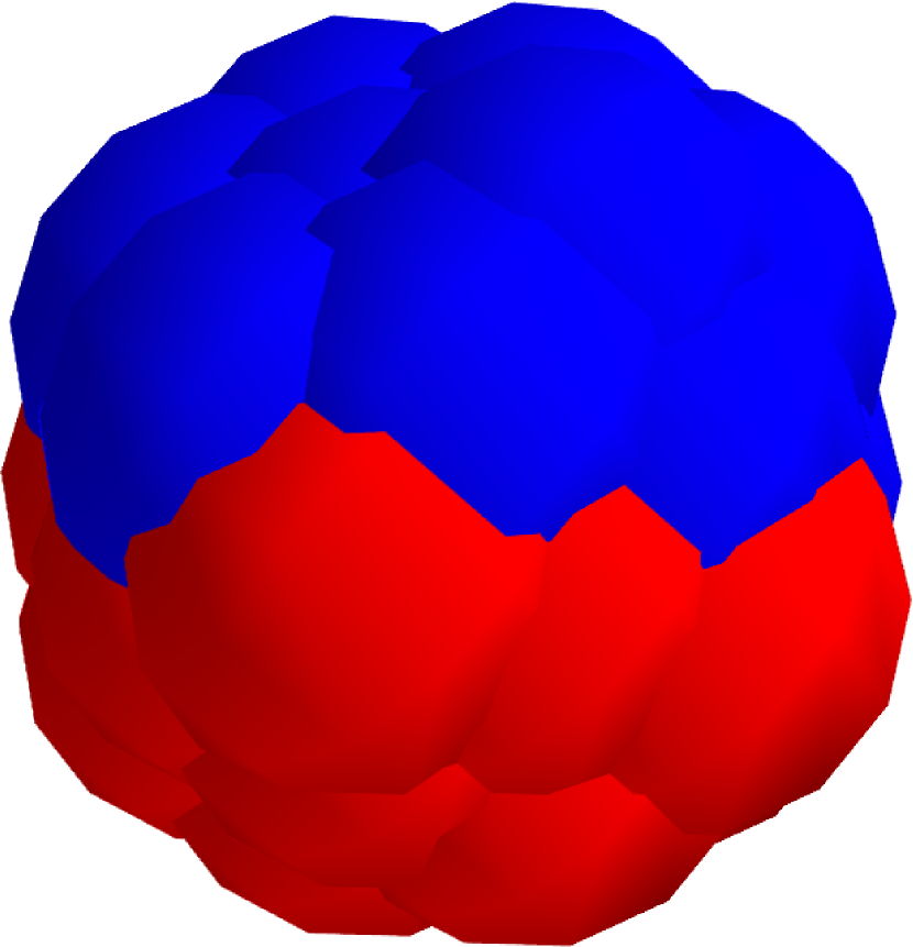
The chemically-powered motor we study is a composite Janus particle comprising a rigid assembly of catalytic and noncatalytic beads (see left panel of Fig. 1). One half of the Janus particle is made of catalytic () beads while the other is half is made from non-active () beads. The solvent in which the Janus particle moves contains, in general, reactive and nonreactive chemical species. The beads in the Janus particle interact with solvent particles through specific intermolecular forces. There are no explicit solvent-solvent intermolecular forces. These are treated by multiparticle collisions 39, 40 as discussed below and described in reviews 41, 42. In addition, the catalytic beads are able to catalyze various chemical reactions that are responsible for the propulsion of the motor. It is the nature of these chemical reactions that is the principal focus of this investigation and the description of how general reactions are implemented on the catalytic sites will be the topic of the next section. Here we specify the nature of the mesoscopic dynamics that governs the evolution of the system.
The evolution of the entire system, the Janus particle and the surrounding solvent is carried out by combining molecular dynamics (MD) with multiparticle collision dynamics (MPCD) 39, 40. In this hybrid evolution scheme, Newton’s equations of motion are integrated for all interacting particles for time intervals . This includes the Janus particle and all solvent particles that interact with it. The remainder of the noninteracting solvent particles free stream during these time intervals. At the time intervals (possibly) reactive multiparticle collisions take place as described in the next subsection.
2.1 Dynamical model for the environment in which the motor moves
The motor environment is modeled by reactive multiparticle collision dynamics (RMPCD) 43, since we wish to allow for the possibility that chemical reactions may occur in the bulk of the solution 36 in addition to the catalytic reactions that occur on the motor itself. RMPCD combines multiparticle velocity-changing collisions among solvent species with local probabilistic rules for changing the identities of those solvent species that participate in reactive events in the bulk of the solution. To carry out the dynamics, at the time intervals the system is partitioned into cells labeled by . We suppose that various reactions, specified by the index , occur in the solution:
| (1) |
The stoichiometric coefficients for reaction are and while and are the rate constants for the forward and reverse reactions. Each reaction, , is taken to occur with probability , where is the set of numbers of the different species in cell , and accounts for the number of different ways the reaction can occur in the cell, with . The rate constants are scaled to account for the cell volume . Reaction rules may be constructed so that mass, momentum and energy are conserved in the reactive events 43.
Once the local reactive events have taken place, all particles in each cell undergo multiparticle collisions where the post-collision velocity of particle in cell , , is given by 39
| (2) |
where is the center of mass velocity of all particles in cell and is a rotation operator for the cell . This algorithm preserves mass, linear momentum and energy within each cell. The combined effect of multiparticle collisions and reactive events is to mimic the effects of many real reactive and nonreactive collisions that take place in the time interval . Since the full hybrid MD-RMPCD preserves the basic conservation laws, hydrodynamic interactions and hydrodynamic flows induced by the self-propulsion are properly described so that this mesoscopic simulation scheme can capture all essential features of the Janus particle and solvent flow motions.
3 Chemical reactions at motor catalytic sites
In this section we show how different types of reaction can be implemented at a mesoscopic level at the catalytic face of the Janus particle. As noted above, in order to respect the basic conservation laws and insure that fluid flows are properly described, the reactions must be constructed to satisfy mass, momentum and energy conservation laws. In earlier studies on sphere dimer motors we restricted our considerations to the simple thermoneutral catalytic reaction, . This reaction amounts to a “coloring” process that changes to on encounters with the catalytic sphere. Mass, momentum and energy are simply conserved in this process. The propulsion arose from the fact that the and species interacted with different intermolecular potentials at the noncatalytic sphere.
The actual catalytic reactions that take place on motor active regions may be quite complex, involving adsorption onto the surface with subsequent formation of products and their release, or binding to active sites in enzymes followed by conformational or other changes and product release. All of these events could involve dissipation of energy into local solvent degrees of freedom, either directly or subsequent to various internal energy transfer processes within the motor. Our mesoscopic treatment of such reactive events coarse grains over most of these molecular-level details. In particular, when the reagents lie within the interfacial zone around the catalytic portion of the Janus particle where intermolecular forces between the reagents and Janus particle beads are non-zero, there is a possibility that a reaction will take place. We subsume all of the reaction details into effective reactive events where reactive species conversion and possible energy distribution in solvent degrees of freedom take place just as the species exit the reactive interfacial zone. The local solvent molecules that participate in any energy exchanges with reactive species are taken to lie in the MPC collision cell that contains the reactive species. Using this strategy it is possible to construct a general class of catalytic reactive events on the active face of the Janus particle 44.
In this coarse-grain description of real reactions catalyzed on the Janus motor, the conservation of momentum and energy in a general reactive event can be written as
| (3) |
for the momentum, where denotes the cell in which the reacting particles are found and the prime again denotes post-reaction quantities. Summing over all particles in the cell allows one to utilize the velocities of solvent particles, other than the reacting ones, to satisfy conservation rules. Energy conservation reads
| (4) |
As described below, in order to model endothermic or exothermic reactions we may associate an internal degree of freedom with the chemical species and in this equation is the internal energy of species . For thermoneutral reactions this internal state label is not needed.
Below we shall make use of the following notation: is the mass of species ; is the sum of the masses of the different species, for instance, and ; is the position of the particle ; is the center of mass position of particles and ; is the unit vector along the – direction; is the velocity of the particle ; is the center of mass velocity of and ; is the relative velocity of and ; is a reduced mass; and is the internal energy associated to a particle . For some of the quantities, for instance the sum of the masses or the center of mass velocity, arbitrary arrangements of indices can be made. For quantities where the order matters, such as or , grouping can be made with a parentheses; e.g., .
The precise manner in which reaction rules are constructed depends on the chemical mechanism one wishes to simulate. We illustrate the procedure by considering two different reaction schemes: an exothermic unimolecular reaction , where is the energy release on reaction, and a dissociation reaction , where represents the Janus particle.
3.1 Exothermic unimolecular reaction
The exothermic unimolecular reaction involves the reactant and product species, and , respectively, interacting with the Janus particle . The reactive and species, while treated as structureless objects, nevertheless carry internal energy labels and , respectively. For example, this is a simplified description of a catalyzed isomerization reaction where reactants and products differ by a free energy difference of . Mass balance requires that the masses of and be equal: . Recall that the Janus particle is a rigid object so that no Janus internal degrees of freedom need to be taken into account. (This condition can be relaxed when flexible self-propelled particles are considered.)
There is considerable freedom in the way one chooses to implement a reactive scheme that accounts for the conservation conditions in Eqs. (3) and (4). For example, for , we may account for the energy change on reaction by changing the post-collision relative kinetic energy of the product molecule and a solvent molecule, and not the Janus particle. In this case the momentum conservation equations take the form,
| (5) |
The second of these equations can be satisfied if the post-collision velocities are given by
| (6) |
where remains to be determined by energy conservation.
Supposing for now, we find that the norm of the relative post-collision velocity depends on the pre-collision relative velocity and also on the difference of internal energies. As remains unmodified by the reaction, the deposition of the excess energy is made in the relative velocity . Equation (4) becomes, in the center-of-mass velocity frame of -,
| (7) |
Since the center-of-mass velocity is not altered during the event, Eq. (7) becomes after some algebra
| (8) |
From Eq. 3.1 we have : . Using and we find
| (9) |
where is the angle between and . We decide to always pick the solution. The angle of may be chosen at random.
As a consequence of the local increase in kinetic energy an inhomogeneous temperature gradient will be generated in the vicinity of the Janus particle. If the interaction energies of the and species with the Janus particle are same, this model exhibits the interesting feature that propulsion will be driven by thermophoresis alone.
3.2 Dissociation reaction
Here we suppose that a dissociation reaction, , is catalyzed by interaction with the rigid Janus particle. The symbols and label the two species molecules that result from the dissociation of . Mass conservation requires that the mass of a molecules is half that of : . Momentum conservation reads,
| (10) |
The energy conservation equation, Eq. (4), can be written in the form,
| (11) |
We may choose to set ; i.e., we may use all of the relative kinetic energy of the system to change the relative energy of . The direction of may be chosen at random. The norm of is then given explicitly by
| (12) |
Other variants of these collision rules may be constructed.
4 Simulation of Janus particle motion
In this section we present the results of simulations of the self-propelled motion of the composite Janus particle when it catalyzes the exothermic unimolecular reaction and dissociation reaction. The simulations were carried out in a cubic box with periodic boundary conditions. This simulation volume contained molecules. The and particles interact with all beads in the Janus particle through repulsive Lennard-Jones potentials,
| (13) |
where and is the Heaviside function. Note that we choose the interactions of both species with both catalytic and noncatalytic beads to be identical; consequently the particles are identical apart from species labels and no propulsion of the Janus particle can arise from the simple thermoneutral reaction considered in previous studies of sphere dimer motors. As described earlier, interactions between the and particles in the environment are accounted for by multiparticle collisions instead of direct intermolecular forces. In the MD portions of the evolution, Newton’s equations of motion are integrated using the velocity Verlet algorithm with a time step . The Shake and Rattle algorithms are used to maintain the rigid bond constraints in the composite Janus particle. In the MPC portions of the evolution, grid shifting is applied at each MPCD step to insure Galilean invariance 45.
All quantities reported below are expressed in simulation units: mass , length , energy and time . In these units the system parameters were: simulation box size, ; MPC time ; average number of particles per MPC cell, 10; reduced temperature, ; and . The choice of the time step depends on the criterion where is the natural time for the Lennard-Jones parameters, . The Janus particle is made from 36 individual spheres, each with Lennard-Jones radius and mass , so that . All realizations of the dynamics started with MPCD steps with an Andersen thermostat 46 at chosen temperature in systems with all particles. We note that for these parameters the thermal velocity for the Janus particle is .
In order to sustain self-propelled motion in the steady state reactants must be supplied to the system and products removed. In the past this has been done by introducing fluxes of these species at the boundaries or far from the motor, or by bulk far-from-equilibrium reactions which are themselves assumed to be sustained by fluxes. (In simple descriptions these species feeds can be accounted for in pool chemical species that may be incorporated into effective rate constants.) In this study we maintain a supply of fresh reagents by taking the reverse of the reaction on the motor to occur in the bulk of the fluid, but with different reaction rates. The reverse reaction for the exothermic reaction is while for the dissociation reaction it is . The reaction rates of both of these reactions were taken to be . These reactions are implemented using the RMPCD algorithm 43. Momentum and energy are obeyed at the cell level as in Eqs. (3) and (4) but without the Janus particle. Energy addition in a cell is obtained by a velocity scaling in the center-of-mass velocity frame.
4.1 Exothermic reaction
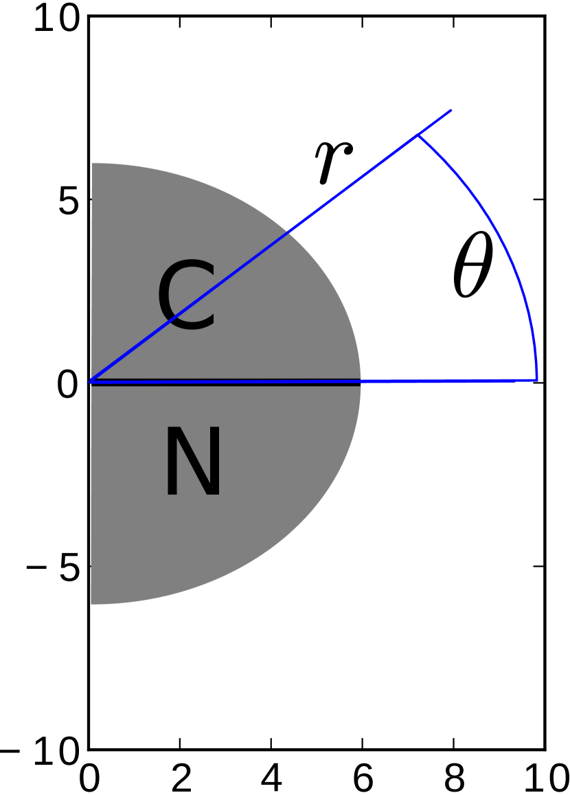
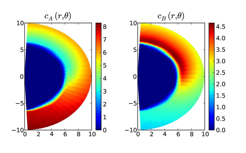
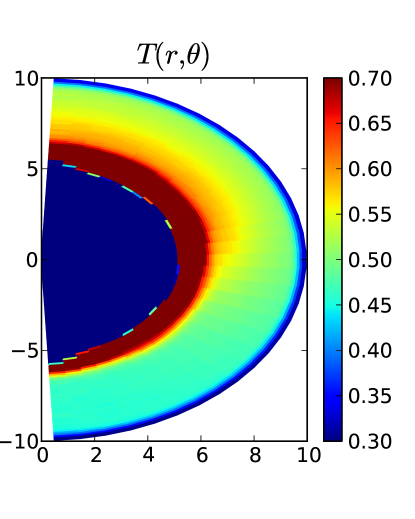
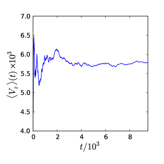
As noted earlier, since the and particles are identical apart from species labels, the only possible source of directed motion (assuming instabilities do not occur) is the temperature gradient across the Janus particle generated by the exothermic reaction. In simulations starting from all molecules in the simulation box, after a transient of time units, the combined effect of reactions at the Janus particle and in the bulk leads to a steady average value of and . For the system in this steady state regime, the number concentrations and are displayed in Fig. 2 and show a strong excess of at the top (catalytic side) of the particle. The polar axis of the Janus particle is used to define a coordinate system that moves along the particle. The definitions of the radius and angle are shown in Fig. 1 (right). The temperature field around the compound is shown in Fig. 3. The temperature is computed cell-wise at regular intervals during the simulations and binned at the center of mass of the corresponding cell. One clearly observes a difference between the and sides of the Janus particle, a sign that a thermal gradient is present in the stationary regime of the system.
The velocity of the self-propelled Janus particle can be determined from the time and ensemble average of , the instantaneous velocity of the center-of-mass velocity projected on the instantaneous unit vector from the center of mass hemisphere to the center of mass of the hemisphere,
| (14) |
where the angular brackets denote an average over realizations of the evolution. When the time argument is omitted, where is the duration of the simulation.
Figure 4 displays . After a short transient, the running average stabilizes around an approximately constant nonzero value, indicating the existence of directed motion. The value of the velocity is positive, consistent with the results obtained by Yang and Ripoll 47 where the thermal gradient is generated externally on the fluid around one sphere of a sphere dimer. The directed velocity is not negligible compared to the thermal velocity and the directed component of the motion plays an important role. Thus, we have demonstrated that the chemically induced temperature gradient by the chemical reaction leads to self-thermophoretic propulsion of the Janus motor.
The behavior for different values of is summarized in Table 1 where and its standard deviation, which characterizes the coherence of between different runs of the same physical conditions, are given. As expected, increasing the energy associated to the reaction increases the propulsion velocity.
4.2 Dissociation reaction
A similar set of simulations was carried out for the dissociation reaction. Figure 5 displays the concentration fields for the and species, showing the production of on the top catalytic side of the Janus particle. As each produces , the maximum value of is much higher than the average density of particles in the system, about particles per MPC cell. The particles diffuse from the side of the Janus particle to the bulk of the fluid where the reverse reaction takes place.
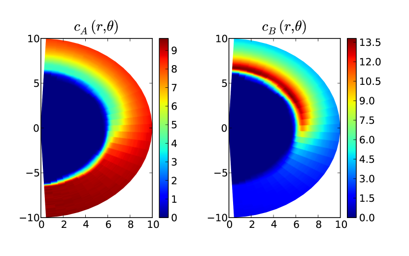
Figure 6 shows [from Eq. (14)]. The gradient of and results in directed motion with the hemisphere of the Janus particle in front. The value of , however, is much lower than the thermal velocity of the Janus particles and the propulsive character can only be observed through averaging.
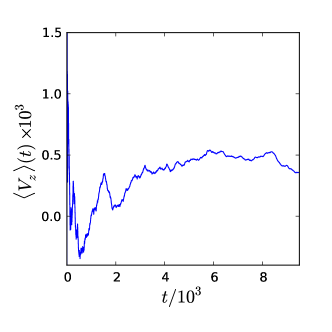
Thus, even though the and particles interact with beads of the Janus particle with the same intermolecular potentials, the excess of particles produced in the reaction provides a mechanism for self-diffusiophoresis and propulsion is observed.
5 Conclusions
The directed motions of small nano- and micron-scale motors that operate by chemically-fueled phoretic mechanisms depend on the nature of the catalytic chemical reactions that occur on the motor. These reactions generate the gradients of fields that are responsible for the propulsion of the motor. The work described in this investigation demonstrated how a variety of chemical mechanisms can be incorporated into a mesoscopic description of the dynamics of the system. One of the important aspects of propulsion by phoretic mechanisms is the correct description of the fluid flow fields that are induced by the motor motion. In order to properly describe the hydrodynamics of the motor environment, the mesoscopic dynamics must preserve the basic conservation laws of mass, momentum and energy conservation. The hybrid MD-MPCD dynamics employed in this study satisfies these criteria. We have shown how different catalytic reactions at the motor surface can be constructed that maintain these conservation laws.
The two examples we have chosen to illustrate the method present interesting features. For both the exothermic unimolecular and dissociation reactions we have chosen to consider the situation where the and reactive species interact with the same intermolecular forces with the Janus particle. This is an special but interesting case that highlights the role that the reaction mechanism plays in the motor propulsion. In the case of the exothermic reaction, the net effect of the reaction is to generate an inhomogeneous temperature gradient in the vicinity of the Janus particle, giving rise to propulsion by a thermophoretic mechanism. This scheme is easily generalized to allow for different interaction potentials for the chemical species on the different hemispheres of the Janus particle. In such a situation both thermophoretic and diffusiophoretic mechanisms will operate, and they can act in either the same or opposite directions. For the dissociation reaction, it is the increased number of product molecules produced in reaction, even when the potential energies of interaction of reactant and products with the Janus particle are the same, that leads to propulsion by self-diffusiophoresis. Again if these potential energies were different the propagation velocity would change.
The work presented here provides a method that allows one to explore self propulsion for a variety of motor geometries and catalytic reaction mechanisms at a mesoscopic level. Through such studies one can investigate motor dynamics on scales where the validity continuum theories should be tested, and study situations where analytical methods are difficult to carry out due to the complex nature of the reaction dynamics.
Acknowledgments: Research supported in part by a grant from the Natural Sciences and Engineering Research Council of Canada. Computations were performed on the GPC supercomputer at the SciNet HPC Consortium. SciNet is funded by: the Canada Foundation for Innovation under the auspices of Compute Canada; the Government of Ontario; Ontario Research Fund - Research Excellence; and the University of Toronto.
References
- Paxton et al. 2004 W. F. Paxton, K. C. Kistler, C. C. Olmeda, A. Sen, S. K. S. Angelo, Y. Cao, T. E. Mallouk, a Paul E. Lammert and V. H. Crespi, J. Am. Chem. Soc., 2004, 126, 13424–13431.
- Fournier-Bidoz et al. 2005 S. Fournier-Bidoz, A. C. Arsenault, I. Manners and G. A. Ozin, Chem. Commun., 2005, 441.
- Paxton et al. 2006 W. F. Paxton, S. Sundararajan, T. E. Mallouk and A. Sen, Angew. Chem. Int. Ed., 2006, 45, 5420.
- Ozin et al. 2005 G. A. Ozin, I. Manners, S. Fournier-Bidoz and A. Arsenault, Adv. Mater., 2005, 17, 3011.
- Wang et al. 2006 Y. Wang, R. M. Hernandez, D. J. Bartlett, M. J. Bingham, T. R. Kline, A. Sen and T. E. Mallouk, Langmuir, 2006, 22, 10451.
- Laocharoensuk et al. 2008 R. Laocharoensuk, J. Burdick and Y. Wang, ACS Nano, 2008, 8, 1069.
- Howse et al. 2007 J. R. Howse, R. A. L. Jones, A. J. Ryan, T. Gough, R. Vafabakhsh and R. Golestanian, Phys. Rev. Lett., 2007, 99, 48102.
- Ke et al. 2010 H. Ke, S. Ye, R. L. Carroll and K. Showalter, J. Phys. Chem. A, 2010, 114, 5462–5467.
- Valadares et al. 2010 L. F. Valadares, Y.-G. Tao, N. S. Zacharia, V. Kitaev, F. Galembeck, R. Kapral and G. A. Ozin, Small, 2010, 6, 565–572.
- Mallouk and Sen 2009 T. E. Mallouk and A. Sen, Sci. Amer., 2009, 300, 72.
- Wang 2009 J. Wang, ACS Nano, 2009, 3, 4.
- Pumera 2010 M. Pumera, Nanoscale, 2010, 2, 1643 1649.
- Paxton et al. 2005 W. F. Paxton, A. Sen and T. E. Mallouk, Chem. Eur. J., 2005, 11, 6462.
- Burdick et al. 2008 J. Burdick, R. Laocharoensuk, P. M. Wheat, J. D. Posner and Y. Wang, J. Am. Chem. Soc., 2008, 130, 8164.
- Ghosh and Fischer 2009 A. Ghosh and P. Fischer, Nano Lett., 2009, 9, 2243.
- Sundararajan et al. 2010 S. Sundararajan, S. Sengupta, M. E. Ibele and A. Sen, Small, 2010, 6, 1479–1482.
- Baraban et al. 2012 L. Baraban, M. Tasinkevych, M. N. Popescu, S. Sanchez, S. Dietrich and O. G. Schmidt, Soft Matter, 2012, 8, 48–52.
- Baraban et al. 2012 L. Baraban, D. Makarov, R. Streubel, I. M nch, D. Grimm, S. Sanchez and O. G. Schmidt, ACS Nano, 2012, 6, 3383–3389.
- Ismagilov et al. 2002 R. F. Ismagilov, A. Schwartz, N. Bowden and G. M. Whitesides, Angew. Chem. Int. Ed., 2002, 41, 652.
- Gibbs and Zhao 2009 J. G. Gibbs and Y.-P. Zhao, Appl. Phys. Lett., 2009, 94, 163104.
- Manesh et al. 2010 K. M. Manesh, M. Cardona, R. Yuan, M. Clark, D. Kagan, S. Balasubramanian and J. Wang, ACS Nano, 2010, 4, 1799–1804.
- Anderson and Prieve 1984 J. L. Anderson and D. C. Prieve, Sep. Pur. Reviews, 1984, 13, 67–103.
- Anderson 1989 J. L. Anderson, Ann. Rev. Fluid Mech., 1989, 21, 61–99.
- Anderson et al. 1982 J. L. Anderson, M. E. Lowell and D. C. Prieve, J. Fluid Mech., 1982, 117, 107–121.
- Anderson and Prieve 1991 J. L. Anderson and D. C. Prieve, Langmuir, 1991, 7, 403–406.
- Jülicher and Prost 2009 F. Jülicher and J. Prost, Eur. Phys. J., 2009, 29, 27–36.
- Golestanian et al. 2005 R. Golestanian, T. B. Liverpool and A. Ajdari, Phys. Rev. Lett., 2005, 94, 220801.
- Golestanian et al. 2007 R. Golestanian, T. B. Liverpool and A. Ajdari, New J. Phys., 2007, 9, 126.
- Howse et al. 2007 J. R. Howse, R. A. L. Jones, A. J. Ryan, T. Gough, R. Vafabakhsh and R. Golestanian, Phys. Rev. Lett., 2007, 99, 048102.
- Popecu et al. 2009 M. N. Popecu, S. Dietrich and G. Oshanin, J. Chem. Phys., 2009, 130, 194702.
- Popecu et al. 2010 M. N. Popecu, S. Dietrich, M. Tasinkevych and J. Ralston, Eur. Phys. J., 2010, 31, 351–367.
- Sabass and Seifert 2012 B. Sabass and U. Seifert, J. Chem. Phys., 2012, 136, 064508.
- Rückner and Kapral 2007 G. Rückner and R. Kapral, Phys. Rev. Lett., 2007, 98, 150603.
- Tao and Kapral 2008 Y.-G. Tao and R. Kapral, J. Chem. Phys., 2008, 10, 770.
- Tao and Kapral 2009 Y.-G. Tao and R. Kapral, J. Chem. Phys., 2009, 131, 024113.
- Thakur and Kapral 2010 S. Thakur and R. Kapral, J. Chem. Phys., 2010, 135, 204509.
- Thakur and Kapral 2010 S. Thakur and R. Kapral, J. Chem. Phys., 2010, 133, 204505.
- Thakur and Kapral 2011 S. Thakur and R. Kapral, Angew. Chem. Int. Ed., 2011, 50, 10165.
- Malevanets and Kapral 1999 A. Malevanets and R. Kapral, J. Chem. Phys., 1999, 110, 8605.
- Malevanets and Kapral 2000 A. Malevanets and R. Kapral, J. Chem. Phys., 2000, 112, 7260.
- Kapral 2008 R. Kapral, Adv. Chem. Phys., 2008, 140, 89.
- Gompper et al. 2009 G. Gompper, T. Ihle, D. M. Kroll and R. G. Winkler, Adv. Polym. Sci., 2009, 221, 1.
- Rohlf et al. 2008 K. Rohlf, S. Fraser and R. Kapral, Comput. Phys. Commun., 2008, 179, 132.
- 44 Applications of similar methods to enzyme kinetics are given in J.-X. Chen and R. Kapral, J. Chem. Phys., 134, 044503 (2011).
- Ihle and Kroll 2001 T. Ihle and D. M. Kroll, Phys. Rev. E, 2001, 63, 20201.
- Noguchi et al. 2007 H. Noguchi, N. Kikuchi and G. Gompper, EPL (Europhysics Letters), 2007, 78, 10005.
- Yang and Ripoll 2011 M. Yang and M. Ripoll, Phys. Rev. E, 2011, 84, 061401.