Full Control of Magnetism in Manganite Bilayer by Ferroelectric Polarization
Abstract
An oxide heterostructure made of manganite bilayers and ferroelectric perovskites is predicted to lead to the full control of magnetism when switching the ferroelectric polarizations. By using asymmetric polar interfaces in the superlattices, more electrons occupy the Mn layer at the -type interface side than at the -type side. This charge disproportionation can be enhanced or suppressed by the ferroelectric polarization. Quantum model and density functional theory calculations reach the same conclusion: a ferromagnetic-ferrimagnetic phase transition with maximal change of the total magnetization can be achieved by switching the polarization’s direction. This function is robust and provides full control of the magnetization’s magnitude, not only its direction, via electrical methods.
pacs:
77.55.Nv; 75.25.Dk; 75.70.CnIntroduction. The control of magnetism using electric fields is a scientifically challenging and technologically important subject that has attracted considerable attention in recent years. Compared with single phase multiferroics (MFE), that typically have a relatively poor performance, composite systems based on oxide heterostructures involving ferroelectric (FE) (or MFE) and ferromagnetic (FM) materials, provide more practical alternatives.Ramesh and Spaldin (2007); Vaz (2012); Hwang et al. (2012) For example, by using antiferromagnetic (AF) MFE layers (e.g. BiFeO3, Cr2O3, YMnO3, etc.), the exchange bias in FM materials attached to the heterostructure can be modulated by the FE ’s or domains.Chu et al. (2008); Béa et al. (2008); Wu et al. (2010); He et al. (2010); Laukhin et al. (2006); Dong et al. (2009, 2011a) In addition, in heterostructures magnetic anisotropies can be tuned by electrical methods, and currents in tunneling magnetic junctions can be affected by the FE barrier layers that also manifest as interfacial magnetoelectricity.Shiota et al. (2012); Wang et al. (2012); Mardana et al. (2011); Gajek et al. (2007); Garcia et al. (2010); Pantel et al. (2012)
Despite their success, from the fundamental viewpoint these controls of magnetism are relatively “weak” effects since the magnetic orders/moments themselves do not change substantially but only their easy axes or domain structures are rotated and tuned.
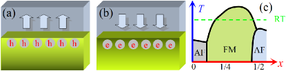
Alternatively, by using the emergent properties of correlated electronic materials, more dramatic magnetoelectric (ME) effects could be envisioned in oxide heterostructures.Ahn et al. (2006) For example, in FE-La1-xSrxMnO3 (LSMO) heterostructures, experiments have found giant changes in conductances triggered by switchable FE ’s.Vaz et al. (2010a, b); Jiang et al. (2012); Leufke et al. (2013); Yin et al. (2013) The associated physical mechanism is believed to be the modulation by the FE field-effect of the local electronic density in manganites near the interfaces (see Fig. 1).Burton and Tsymbal (2011, 2009); Dong et al. (2011b); Chen and Ismail-Beigi (2012)
However, typically this effect can only penetrate no more than unit cells (u.c.) in manganites, before the effect is almost fully screened.Burton and Tsymbal (2011, 2009); Dong et al. (2011b); Chen and Ismail-Beigi (2012) Then, the proposed magnetic phase transitions occur only within a few interfacial layers, inducing a relatively small modification of the total magnetization ().Vaz et al. (2010a, b); Jiang et al. (2012); Leufke et al. (2013); Yin et al. (2013)
Another issue of much relevance in oxide heterostructures is the polar discontinuity, which is emphasized for interfaces between insulators (e.g. LaAlO3-SrTiO3).Nakagawa et al. (2006) But this effect is often neglected in heterostructures with conductive components, e.g. LSMO, since it will be screened within a few u.c. similarly as in the FE field-effect.
Model system. In this Rapid Communication, by reducing the thickness of the manganite component to bilayer size, both the FE field effect and polar discontinuity becomes prominent despite the metallicity of the manganite. A direct advantage of bilayers is the maximized interface/volume ratio (up to ) for manganites that allows each manganite layer to be fully controlled by the FE . More importantly, the neighboring asymmetric polar interfaces break the symmetry of the FE field-effect in periodic SLs, conceptually different from results in symmetric interfaces in SLs or single interfaces in simple heterostructures. The asymmetric design and ultra-thin bilayers are crucial to achieve the full control of magnetism reported in our study.
As our model system, SLs stacked along the conventional (001)-direction made of MnO3-TiO3 (=divalent cation, =trivalent rare-earth, and =divalent alkaline-earth) are here considered, as sketched in Fig. 2(a). The manganite components are thin involving only bilayers while the FE titanate is assumed to be slightly thicker to maintain its .Jiang et al. (2012) Asymmetric polar interfaces are used: the interfaces with TiO2-O-MnO2 and TiO2-O-MnO2 will be referred to as -type and -type interfaces, respectively. The -type interface, with a positively charged (O)(1-x)+ layer, will attract electrons to its nearest-neighbor (NN) MnO2 layer, while the -type interface will repel electrons away from the interface. Therefore, even without ferroelectricity the asymmetric interfaces already modulate the electronic density and electrostatic potential within the manganite bilayers.
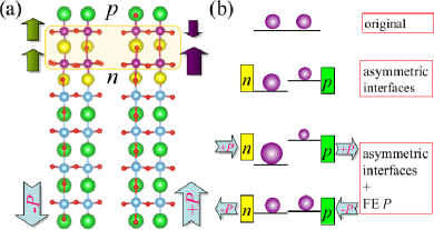
When the FE points to the -type interface (the case), the electrostatic potential difference between the two MnO2 layers will be further split, thus enhancing the charge disproportionation. However, when the FE points to the -type interface (the case) the electrostatic potential from the polar interfaces will be partially compensated, thus suppressing the electronic disproportionation. The above processes are summarized in Fig. 2(b). In the ideal limit of case, if these two effects (asymmetric polar interfaces vs. FE ) could be fully balanced, both the electrostatic potential and electronic distribution in the manganite bilayers would become uniform. By suitable combinations of couplings, this nearly full compensation is possible since a robust FE perovskite (e.g. PbZryTi1-yO3 or Ba1-ySryTiO3) has a large , which is equivalent to a surface charge of electrons per u.c. that can be tuned by adjusting the concentration to fit the polar charge (O)(1-x)+ which is very similar in magnitude. Below, this ideal case limit is adopted in the model simulations (with FE surface charge electrons per u.c.) to achieve a clear physical scenario and magnify contrasting effects when compared with the case. Deviations from this ideal limit lead to qualitatively similar results in practice.
Methods. The two-orbital double-exchange model with both the NN superexchange and electron-lattice coupling is here employed for the manganite bilayer components. Dagotto et al. (2001) The effects of the FE and polar layers are modeled by an electrostatic potential.Dong et al. (2011b) A cluster is used to simulate the manganite bilayer. In-plane “twisted” boundary conditions (BC) are adopted in the zero-temperature () self-consistent calculations to reduce finite-size effects,Dong et al. (2012) while periodic BC are used in the computer time-consuming finite- Monte Carlo (MC) simulations. The average electronic density () in the manganite bilayer is chosen as , corresponding to a regime that typically has a FM ground state in manganites. All energies will be in units of , the double-exchange hopping amplitude ( eV for LSMO).Dagotto et al. (2001); Dong et al. (2011b) In addition, DFT calculations were performed on the BaTiO3-LSMO SL using the Vienna ab initio Simulation Package (VASP).Kresse and Hafner (1993); Kresse and Furthmüller (1996) Details of model Hamiltonian and numerical methods are in the supplementary material.See EPAPS Document No. X-XXXXXX-XXX-XXXXXX for supplementary material
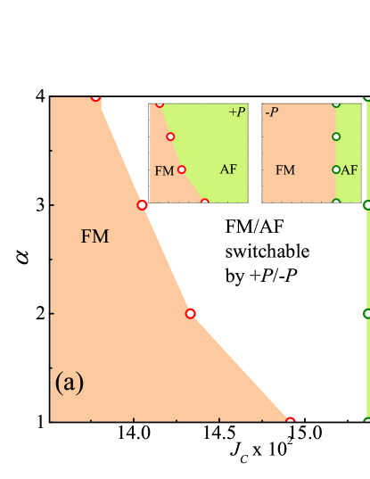
Zero- self-consistent calculation. First, the electrostatic potentials affecting the electrons and the associated densities (: is the layer index) are calculated at self-consistently via the Poisson equation and the model Hamiltonian. Then, the energies of the FM and AF states are compared to determine the ground state under . As shown in Fig. 3(a), in the case the ground state is FM if the interlayer superexchange coupling is smaller than . In the case, the ground state is AF for a larger than specific values that depend on the dielectric constant () of manganite bilayers, all lower than for all ’s studied here. Therefore, within the middle region the magnetic ground state can switch from FM to AF by switching the direction of the FE . Strictly speaking, here the AF order is ferrimagnetic once the magnetic moments from the electrons are taken into account, since . Thus, the magnetic switch occurs between a FM state with strong and an AF state with a much weaker . Even with this caveat, the variation in created by the switch remains quite significant: ideally.
It is interesting to compare the magnetic switch effects described here against the interfacial phase transitions studied in thick manganite-FE heterostructures.Burton and Tsymbal (2011, 2009); Dong et al. (2011b); Chen and Ismail-Beigi (2012) As shown in Fig. 3(b), in thick manganite layers the local electronic densities of the first two-interfacial-layers can both be substantially enhanced or suppressed by the field effect. Then, the exchange coupling between the first two-interfacial layers can be intuitively guessed from the bulk’s phase diagram. For example, if the local densities of both layers are close to , it is natural to expect locally an A-type AF state.Dagotto et al. (2001) By contrast, this expectation is unrealistic in the bilayer case, since once is close to then must be close or below . In this sense, the FE field-effect in the bilayers is anomalous, with strong interference effects between the -/- interfaces. And the magnetic coupling between the and layers is unclear a priori. Thus, in spite of similarities, the underlying mechanism of magnetic switch in the bilayers studied here is not qualitatively the same as for the phase transitions reported in thicker cases. Furthermore, due to the compensation effect between the neighboring - and -type interfaces, the charge modulation and electrostatic potential between the top and bottom layers in bilayers are obviously weaker than for thicker cases (more details in supplementary materials).See EPAPS Document No. X-XXXXXX-XXX-XXXXXX for supplementary material
Finite-T MC simulation. The calculations described thus far relied on the comparison of energies between the ideal FM and AF phases, which is intuitive correct but needs confirmation using more powerful many-body techniques. In the following, finite- MC simulations will be employed to confirm the previous results. The electron-phonon coupling is also taken into account in the MC simulation. Here the electron-phonon coupling coefficient is chosen as and the superexchange coefficients as in-plane and out-of-plane, which are realistic values from previous studies of manganites.Dagotto et al. (2001); Dong et al. (2011b)
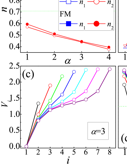
In this more rigorous approach, the switch from FM to AF states is still observed. Fig. 4(a) shows the layer-resolved in-plane spin structure factors at wavevector (,) corresponding to in-plane “FM” order. All curves show paramagnetic (PM) to “FM” transitions although at different ’s. In the case, the two layers transit synchronically since the electronic density is uniform. By contrast, in the case, the two layers transit separately. Thus, in the mid- region, the st layer becomes “FM”, but the nd layer remains PM.
The averaged NN spin correlations between layers are shown in Fig. 4(b). Clearly, with decreasing the and cases show opposite tendencies (AF vs. FM coupling). Thus, the transitions revealed in Fig. 4(a) are PM-FM for the case but PM-AF (ferrimagnetic) for the case. The average ’s of the textures are presented in Fig. 4(c), which also display a clear contrast. In the case, there is a peak in in the mid- region suggesting a ferrimagnetic transition, with a small but nonzero up to low temperatures.
The ’s observed in these MC simulations are quite high. For a rough estimation, if the of the bilayer () in the case is used to fit the ( K) corresponding to LSMO (),Dagotto et al. (2001) the upper-limit working () for the magnetic switch can reach up to K. Also, if the energy unit is estimated to be eV for LSMO,Dagotto et al. (2001) the upper-limit working grows to K. Both these estimations suggest that our proposed setup works at room-. Of course, finite-size extrapolations are difficult via time-consuming MC techniques.
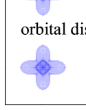
Compared with the self-consistent calculation using two preset candidate phases, the unbiased finite- MC simulation is more reliable. For example, in our MC simulation, the robust electron-phonon coupling is essential to stabilize the AF phase while it is not required in the self-consistent case. In bulk undoped manganites such as LaMnO3, the staggered / orbital order (OO) associated with the Jahn-Teller distortion is prominent and crucial for the A-type AF state.Dagotto et al. (2001); Hotta (2006) This OO also plays an important role here in the bilayers. As shown in Fig. 4(d-e), the case displays different OO for the two layers. The first layer, which is close to the undoped case, shows the /-like OO (Fig. 4(d)). However, in the second layer, with an average electronic density slightly below , another type of OO is present which agrees with the -type OO (Fig. 4(e)) known to exist in half-doped manganites.Dagotto et al. (2001); Hotta (2006) Both these two OO’s have strong orbital lobes lying in-plane, which enhances (suppresses) the in-plane (out-of-plane) double-exchange processes. Thus, this hybrid OO’s combination is advantageous to stabilize the AF order in such a bilayer. By contrast, the case shows uniform orbital occupancy (Fig. 4(f)), which prefers the FM state.
DFT study. The model simulations described above have been carried out in the ideal limit (i.e. with full compensation between FE and polar interfaces). However, as stated before, our predictions are not restricted by this condition. To confirm the robustness of our proposal, a preliminary ab-initio DFT calculation was performed to verify the FE control of magnetic order.
| FE | Order | Energy | |||
|---|---|---|---|---|---|
| FM | |||||
| AF | |||||
| FM | |||||
| AF |
The (BaTiO3)4-(LSMO)2 () SL was studied as the model system, as sketched in Fig. 2(a). According to the model study described above, an anisotropic superexchange is necessary for a switch function. In the DFT study, an in-plane tensile strain (for manganite) can induce such an effect. Thus, here the in-plane lattice constant of the SL is fixed to be Å to fit the KTaO3 substrate,111Some other combinations of substrates/manganites/titantes have also been tested. A proper in-plane tensile is important to tune the subtle balance between the FM and AF orders, namely the switching function. which can provide tensile strain to the LSMO bilayer. As shown in Table I, the calculated energies indicate that the ground state is FM under the condition, but it switches to the AF state by using . The local magnetic moments also show a significant modulation in magnitude, implying the cross impact of the FE and polar interfaces combination. The nonzero net of the AF state in the DFT study suggests a ferrimagnetic state. In spite of this caveat, the FM state displays a much larger net , giving rise to a modulation by switching , in agreement with the model calculations described above. Then, the DFT study also confirms the FE control of magnetism, despite the modifications of the density and the use of a non-ideal condition. More details of our DFT study can be found in the supplementary material.See EPAPS Document No. X-XXXXXX-XXX-XXXXXX for supplementary material
Note. Finally, it is important to remark that although the notorious “dead layers” problem in real ultra-thin manganite films may suppress ferromagnetism significantly,Huijben et al. (2008); Tebano et al. (2008) recent experiments indicate that the “dead layers” of LSMO should be thinner than u.c. per interface in the SL geometries.Kourkoutis et al. (2010); Gray et al. (2010) The latest experiments and theoretical simulations also show that local non-stoichiometry is responsible to “dead layers”.Peng et al. (2013); Song et al. (2013); Wang et al. (2013) Thus, with further improvements in the fabrication techniques “alive” manganite bilayers in SLs will be possible, as designed in our model. Recent experimental and theoretical progress in the “dead layers” issue is shown in the supplementary material.See EPAPS Document No. X-XXXXXX-XXX-XXXXXX for supplementary material .
In summary, our theoretical studies, using both models and ab-initio methods, predict the full control of magnetism when manganite bilayers are coupled to FE polarizations. The combination of FE polarization and asymmetric polar interfaces gives rise to two competing magnetic states: ferromagnetic and ferrimagnetic ones. The change of the total magnetization is remarkable (up to ) and may persist to room temperatures. Although our study uses titanates as the FE layers, the physical mechanism is general and applicable to other ferroelectrics. Similar effects are expected when using manganites at other doping concentrations and with other bandwidths, increasing the range of compounds where our proposal can be realized. Therefore, our work provides a potential design to pursue the full control of magnetism in oxide heterostructures.
S.D. was supported by the 973 Projects of China (2011CB922101), NSFC (11004027, 11274060), NCET, and RFDP. E.D. was supported by the U.S. DOE, Office of Basic Energy Sciences, Materials Sciences and Engineering Division.
I Details of model simulations
I.1 Model Hamiltonian and parameters
According to Refs. Dagotto et al., 2001; Dagotto, 2002, the Hamiltonian of the two-orbital double-exchange model reads as:
| (1) | |||||
The first term denotes the standard double-exchange hopping process for the electrons between nearest-neighbor sites and . The operators () annihilate (create) an electron at the orbital of the lattice site . Within the standard infinite Hund coupling approximation, the spin of the electrons is always parallel to the spin of the localized degrees of freedom , generating the Berry phase as , where and are the polar and azimuthal angles of the spins, respectively. The three nearest-neighbor (NN) hopping directions are denoted by . Two orbitals (: and : ) are involved in the double-exchange process for manganites, with the hopping amplitudes given by:
| (6) | |||||
| (11) | |||||
| (16) |
The hopping will be considered as the unit of energy. This hopping can be roughly estimated to be eV.Dagotto et al. (2001); Dagotto (2002)
The second term of the Hamiltonian is the antiferromagnetic superexchange interaction between the NN spins. The typical value of the superexchange coupling is in the order of based on a variety of previous investigations for bulk manganites.Dagotto et al. (2001); Dagotto (2002) In the Monte Carlo simulation described in the main text, an in-plane isotropic is adopted since the bilayer growing along the (001) direction has a tetragonal-like symmetry. However, the exchange along -axis is different from those in-plane especially when strain from the substrate is present.
The third term stands for the electron-lattice interaction, with being a dimensionless coupling. Both the breathing mode () and two Jahn-Teller modes ( and ) are considered here. stands for the change in the length of the O-Mn-O bonds along a particular axis . is the local electronic density. The () and () are orbital pseudospin operators.
In the last term, is the on-site electrostatic potential, which is layer-dependent. In the =0 self-consistent calculation, is determined via the one-dimensional Poisson equation. In the Poisson equation, is used as the Coulomb coefficient. is inversely proportional to the dielectric constant [), where is the lattice constant and is the dielectric constant]. When calculating the total energy, the Coulombic potential affecting the A-site cations and ferroelectric polarization will also been added. Readers can find more details regarding the electrostatic potential and energies in one of our previous publications.Dong et al. (2011b)
A cluster is used to simulate the manganite bilayer. In-plane twisted boundary conditions are adopted in the zero-temperature self-consistent calculations to reduce finite-size effects.Dong et al. (2011b) while periodic boundary conditions are used in the computer time-consuming finite-temperature Monte Carlo simulations.
I.2 Zero-temperature simulations
For a fixed set of parameters, the electronic density and potential are calculated self-consistently at zero-temperature. Here both the FM and AF backgrounds are considered and several values of the manganite dielectric constant were tested, which are characterized by a Coulombic coefficient ( corresponds to ).Dong et al. (2011b)
.
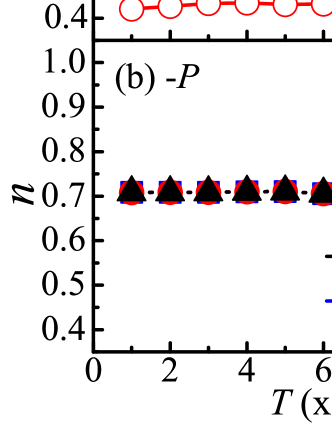
As shown in Fig. 5(a), in the case the electronic densities are split between the two layers with the higher value near the -type interface (=). Increasing the Coulombic coefficient increases further this splitting, inducing also a large potential modulation [Fig. 5(b)].Dong et al. (2011b) FM and AF spin orders [insets of Fig. 5(b)] are here adopted for comparison, and both give quite similar and with only small differences. Therefore, as a first-order approximation the electrostatic modulation from the FE and polar interfaces will be assumed to be independent of the manganite bilayer spin order. For the case, and are uniform (not shown) since the ideal limit is used.
By using the same process, other superlattices with thicker manganite layers can also be calculated, as shown in Fig. 5(c-d). It is clear that the bilayer one has the weakest charge disproportion and potential modulation, because the electrostatic potential is approximately in proportional to the thickness of manganite layers. This weakest charge disproportion will also make the phase transition in bilayers not as easy to occur as in the thicker layers studied before.Dong et al. (2011b) Fine tuning of orbital order and anisotropic exchange, as carried out in our work, are essential in the bilayer case but not required in thicker cases.
I.3 Finite-temperature Monte Carlo simulations
The Monte Carlo simulation is applied to the classical spin variables and the lattice distortions ( or , while is frozen at the original value), while exact diagonalization is used for the fermionic sector (i.e. for the electrons). The first Monte Carlo steps are adopted for thermal equilibrium and the following Monte Carlo steps are used for measurements. Readers can find more details of the Monte Carlo method employed in the present work in Refs. Dagotto et al., 2001; Dagotto, 2002
During the Monte Carlo simulation, the electrostatic potential is fixed as a proper value considering the values shown in Fig. 5(b). This simplification depends on two preconditions: the electrostatic potential must be not affected too much by 1) the magnetic state and 2) temperature. The first one has been partially confirmed already, as shown in Fig. 5(a), and will be further reconfirmed below, as shown in Fig. 6(a). By using FE materials with high Curie temperatures, then the second one will also be not difficult to be satisfied.
As shown in Fig. 6(a), the case gives a robust charge disproportion which is almost temperature-independent in the studied range despite the magnetic-magnetic disorder-ordering transition. This result is self-consistent with the fixed electrostatic potential used in the Monte Carlo simulation, which also coincides with the above zero-temperature result. Meanwhile, the case always give a uniform charge distribution between two layers (Fig. 6(b)).
II Details of the DFT calculations
The density functional theory (DFT) calculations were here performed based on the projected augmented wave (PAW) pseudopotentials using the Vienna ab initio simulation package (VASP).Blöchl et al. (1994); Kresse and Hafner (1993); Kresse and Furthmüller (1996) The valence states include the orbitals , , , , and for Ba, Ti, La, Sr, Mn and O, respectively. The electron-electron interaction is described using the generalized gradient approximation (GGA) method. The energy cutoff is eV and the -center -mesh is for the superlattice.
According to the model study, an isotropic superexchange is needed, with a weak in-plane coupling and a strong out-of-plane coupling. This effect can be fulfilled by using an in-plane tensile strain for the manganite bilayer. In the present study, cubic KTaO3 is chosen as the substrate with a lattice constant Å. In addition, this substrate can also give a compressive strain to BaTiO3, which can enhance its ferroelectric polarization.
First, the atomic positions and lattice constants along the -axis were relaxed for pure La0.75Sr0.25MnO3 and BaTiO3 (with spontaneous ferroelectric polarization) respectively, by fixing the in-plane crystal lattice constants as Å to match the KTaO3 substrate.
Then, a superlattice structure consisting of layers of BaTiO3 and a La0.75Sr0.25MnO3 bilayer (for a total of atoms) is stacked along the [001] axis, according to their individual structures. Due to the doping of Sr, there are two types of interfaces: (1)…-TiO2-LaO-MnO2-La0.5Sr0.5O-MnO2-BaO-… and (2)…-TiO2-La0.5Sr0.5O-MnO2-LaO-MnO2-BaO-… . The first one has a stronger polar interface, which will be studied in the present work.
To simulate a robust in such a thin ferroelectric layer with asymmetric polar interfaces, the atomic positions for BaTiO3 are frozen during the atomic relaxation. Otherwise the state may be depolarized by the polar interfaces. In practice, this issue can be solved by using a little thicker ferroelectric layers or poling it using electric fields. In fact, with good ferroelectric materials (e.g. PbZr1-yTiyO3), can be both stabilized even when its thickness is only nm when attached to LSMO.Jiang et al. The atoms of La0.75Sr0.25MnO3 and the interfacial linking oxygens are relaxed under different magnetic orders (ferromagnetic and A-type antiferromagnetic) and , as the total energies converge. Then, the total energies and magnetization are calculated for the relaxed structures.
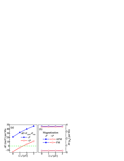
In addition, the GGA+ method in the Dudarev approachDudarev et al. (1998) was also tested by adopting the above relaxed lattices. The Hubbard was added to the Mn’s orbitals. As shown in Fig. 7(a), the switching between the FM and AF states can occur in the low- region (, eV), but it becomes “un-switchable” in the large- region since the FM configurations dominate for both polarization directions. In other words, with increasing ’s the system develops a stronger FM tendency, in agreement with previous DFT calculations.Luo et al. (2007); Chen and Ismail-Beigi (2012)
In spite of this potential “problem”, the energy difference between the FM and AF states in the meV/per Mn scale suggests that the switching could still occur in practice by simply fine tuning other parameters in the experiments. For example, one can use LSMO with a little higher doping chosen to be closer to the AF state according to Ref. Chen and Ismail-Beigi, 2012. In our current DFT calculation, we can only deal with the case due to cluster size limitations. But in real experiments, considering the many magnetic phases of manganites and rich phase diagrams, it is certainly possible to find a proper material and proper substrates to realize the giant switch effect proposed here. In other words, by no means our ideas are restricted to .
In addition, some previous DFT studies found that the GGA method is better than GGA+ for doped metallic manganites,Luo et al. (2007); Burton and Tsymbal (2009) and a weak ( eV) was found to be better than a large .Chen and Ismail-Beigi (2012) Then, the GGA+ results suggesting that at large the switch does not occur may need revision as well.
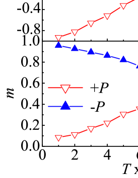
As shown in Fig. 7(b), the total magnetizations of the FM and AF states are almost unaffected by , implying that the giant modulation of the magnetization is quite stable if it can be realized in experiments.
The spin-orbit coupling, which is weak and not important in this case, is not included in the DFT calculations.
III The “dead layer” problem of manganite ultra-thin films
In ultra-thin manganite films a practical problem is caused by the presence of the so-called “dead layers”. When the thickness of a LSMO thin film with composition is reduced to just a few unit cells (u.c.) the film becomes non-magnetic and insulating. This is surprising because at this composition LSMO is FM and metallic when in bulk form. For example, in 2008 Huijben et al. Huijben et al. (2008) and Tebano et al. Tebano et al. (2008) it has been reported that for LSMO thin films grown on SrTiO3 (STO) with a thickness below u.c., the metallicity disappeared. However, despite this reported insulating behavior, thin films of u.c. remained FM although with a reduced from K to K and with a saturated magnetization reduction to of the expected values.Huijben et al. (2008); Tebano et al. (2008)
It is very important to understand and overcome this “dead layer” problem considering the potential applications of LSMO films in spintronics. For the results reported in the present publication this effect is particularly important since our main conclusions have been obtained using bilayers of LSMO, that may potentially contain dead layers. However, there is considerable controversy regarding the accurate value of the critical thickness and its underlying mechanism. The critical thickness has been found to depend strongly on several experimental technical aspects, such as the oxygen partial pressures used during the growth, the type of substrates, annealing processes employed, and even on laser spots in the PLD growth. Thus, the critical thickness varies from group to group and even within the same group.
From the theoretical perspective, there are no intrinsic reasons why LSMO thin films grown on a STO substrate must be “dead” if the crystal structure is without any defects. Both model Hamiltonian and DFT calculations have reported a robust FM state for a few LSMO layers grown on STO, e.g. as in our current work and Ref. Wang et al., 2013. In this sense, the underlying mechanism for the presence of dead layers is likely related with imperfections in the LSMO ultra thin-films such as atomic intermixing.
Although in Refs. Huijben et al., 2008; Tebano et al., 2008, the orbital reconstruction was associated with the existence of dead layers, recent experiments attributed an even larger contribution to local non-stoichiometric effects. For example, in Ref. Peng et al., 2013, compelling evidence was showed that the intrinsic oxygen vacancy formation was the reason for the presence of dead layers. And in Refs. Song et al., 2013; Li et al., 2012, the layer-dependent non-stoichiometry was found to be affected by details of the interface and surface.
As discussed in Ref. Peng et al., 2013, this local non-stoichiometry may be caused by the internal electrostatic field induced by the polar discontinuity effect between the LSMO/substrate and LSMO/vacuum interfaces. Thus, with the continuous advances in the experimental techniques and with a better understanding of the underlying mechanism, it is reasonable to expect that the dead layer effect will be further suppressed in the future.
The polar discontinuity related with the LSMO/vacuum interface can be easily eliminated in superlattices with repeated interfaces, as used in our model system. In fact, recent experiments reported that the intrinsic critical thickness of the dead layers has an upper bound of just u.c. per interface in LSMO/STO superlattices.Kourkoutis et al. (2010) In fact, u.c. LSMO thin films exhibited clear ferromagnetism above room temperature and remained metallic below the Curie temperature, even in the presence of some interfacial interdiffusion.Gray et al. (2010); Kourkoutis et al. (2010) Although these two experiments did not study even thinner cases, it is likely that u.c. is not itself the critical limit for dead layers in LSMO/STO superlattices since its Curie temperature and magnetization are robust. In other words, it is to be expected that the ferromagnetism will survive in even thinner cases.
Also, the polar discontinuity related with the LSMO/substrate interface can be partially eliminated with modern technology. For example, in Refs. Peng et al., 2013; Boschker et al., 2012, the magnetism and conductance of LSMO thin films were improved by careful interfacial engineering, even in the presence of open surfaces.
Finally, it is important to remark that the polar electrostatic driving force to form the aforementioned intrinsic defects is weaker in the present bilayer case than in thicker ones. This tendency has also been observed in our simulation, as shown in Fig. 5(c-d). According to the polar catastrophe scenario,Nakagawa et al. (2006) the electrostatic potential between the top and bottom layers increases with the thickness of the films. In bilayers only two layers are neighbors and the interference between these neighboring interfaces significantly suppresses the polar electrostatic potential, which will be helpful to further eliminate defects. Experimental evidence is that in Ref. Song et al., 2013 the layer-resolved non-stoichiometry was weaker in the u.c. case than in the u.c. one. In addition, the polar electrostatic effect has already been taken into account in our bilayer simulations.
In summary, recent experimental progress has clearly indicated that the “dead layer” problem of LSMO thin films is mainly related with the quality of the interface. Thus, it is a technical problem. This problem is weaker in superlattices, as described in the present study. And the critical thickness of the “dead layers” has been significantly reduced in recent years and this progress is going on. In fact, in the past an analogous story developed in the context of dead layers in ferroelectric thin films, which also puzzled researchers for several years. This effect has been successfully solved due to improvements in the preparation of the samples.Fong et al. (2004)
References
- Ramesh and Spaldin (2007) R. Ramesh and N. A. Spaldin, Nat. Mater. 6, 21 (2007).
- Vaz (2012) C. A. F. Vaz, J. Phys.: Condens. Matter 24, 333201 (2012).
- Hwang et al. (2012) H. Y. Hwang, Y. Iwasa, M. Kawasaki, B. Keimer, N. Nagaosa, and Y. Tokura, Nat. Mater. 11, 103 (2012).
- Chu et al. (2008) Y.-H. Chu, L. W. Martin, M. B. Holcomb, M. Gajek, S.-J. Han, Q. He, N. Balke, C.-H. Yang, D. Lee, W. Hu, Q. Zhan, P.-L. Yang, A. Fraile-Rodríguez, A. Scholl, S. X. Wang, and R. Ramesh, Nat. Mater. 7, 478 (2008).
- Béa et al. (2008) H. Béa, M. Bibes, F. Ott, B. Dupé, X.-H. Zhu, S. Petit, S. Fusil, C. Deranlot, K. Bouzehouane, and A. Barthélémy, Phys. Rev. Lett. 100, 017204 (2008).
- Wu et al. (2010) S. W. Wu, S. A. Cybart, P. Yu, M. D. Rossell, J. X. Zhang, R. Ramesh, and R. C. Dynes, Nat. Mater. 9, 756 (2010).
- He et al. (2010) X. He, Y. Wang, N. Wu, A. N. Caruso, E. Vescovo, K. D. Belashchenko, P. A. Dowben, and C. Binek, Nat. Mater. 9, 579 (2010).
- Laukhin et al. (2006) V. Laukhin, V. Skumryev, X. Martí, D. Hrabovsky, F. Sánchez, M. V. García-Cuenca, C. Ferrater, M. Varela, U. Lüders, J. F. Bobo, and J. Fontcuberta, Phys. Rev. Lett. 97, 227201 (2006).
- Dong et al. (2009) S. Dong, K. Yamauchi, S. Yunoki, R. Yu, S. Liang, A. Moreo, J.-M. Liu, S. Picozzi, and E. Dagotto, Phys. Rev. Lett. 103, 127201 (2009).
- Dong et al. (2011a) S. Dong, Q. F. Zhang, S. Yunoki, J.-M. Liu, and E. Dagotto, Phys. Rev. B 84, 224437 (2011a).
- Shiota et al. (2012) Y. Shiota, T. Nozaki, F. Bonell, S. Murakami, T. Shinjo, and Y. Suzuki, Nat. Mater. 11, 39 (2012).
- Wang et al. (2012) W.-G. Wang, M. Li, S. Hageman, and C. L. Chien, Nat. Mater. 11, 64 (2012).
- Mardana et al. (2011) A. Mardana, S. Ducharme, and S. Adenwalla, Nano Lett. 11, 3862 (2011).
- Gajek et al. (2007) M. Gajek, M. Bibes, S. Fusil, K. Bouzehouane, J. Fontcuberta, A. Barthélémy, and A. Fert, Nat. Mater. 6, 296 (2007).
- Garcia et al. (2010) V. Garcia, M. Bibes, L. Bocher, S. Valencia, F. Kronast, A. Crassous, X. Moya, S. Enouz-Vedrenne, A. Gloter, D. Imhoff, C. Deranlot, N. D. Mathur, S. Fusil, K. Bouzehouane, and A. Barthélémy, Science 327, 1106 (2010).
- Pantel et al. (2012) D. Pantel, S. Goetze, D. Hesse, and M. Alexe, Nat. Mater. 11, 289 (2012).
- Ahn et al. (2006) C. H. Ahn, A. Bhattacharya, M. D. Ventra, J. N. Eckstein, C. D. Frisbie, M. E. Gershenson, A. M. Goldman, I. H. Inoue, J. Mannhart, A. J. Millis, A. F. Morpurgo, D. Natelson, and J.-M. Triscone, Rev. Mod. Phys. 78, 1185 (2006).
- Vaz et al. (2010a) C. A. F. Vaz, J. Hoffman, Y. Segal, J. W. Reiner, R. D. Grober, Z. Zhang, C. H. Ahn, and F. J. Walker, Phys. Rev. Lett. 104, 127202 (2010a).
- Vaz et al. (2010b) C. A. F. Vaz, Y. Segal, J. Hoffman, R. D. Grober, F. J. Walker, and C. H. Ahn, Appl. Phys. Lett. 97, 042506 (2010b).
- Jiang et al. (2012) L. Jiang, W. S. Choi, H. Jeen, T. Egami, and H. N. Lee, Appl. Phys. Lett. 101, 042902 (2012).
- Leufke et al. (2013) P. M. Leufke, R. Kruk, R. A. Brand, and H. Hahn, Phys. Rev. B 87, 094416 (2013).
- Yin et al. (2013) Y. W. Yin, J. D. Burton, Y. Kim, A. Y. Borisevich, S. J. Pennycook, S. M. Yang, T. W. Noh, A. Gruverman, X. G. Li, E. Y. Tsymbal, and Q. Li, Nat. Mater. 12, 397 (2013).
- Burton and Tsymbal (2011) J. D. Burton and E. Y. Tsymbal, Phys. Rev. Lett. 106, 157203 (2011).
- Burton and Tsymbal (2009) J. D. Burton and E. Y. Tsymbal, Phys. Rev. B 80, 174406 (2009).
- Dong et al. (2011b) S. Dong, X. T. Zhang, R. Yu, J.-M. Liu, and E. Dagotto, Phys. Rev. B 84, 155117 (2011b).
- Chen and Ismail-Beigi (2012) H. Chen and S. Ismail-Beigi, Phys. Rev. B 86, 024433 (2012).
- Dagotto et al. (2001) E. Dagotto, T. Hotta, and A. Moreo, Phys. Rep. 344, 1 (2001).
- Nakagawa et al. (2006) N. Nakagawa, H. Y. Hwang, and D. A. Muller, Nat. Mater. 5, 204 (2006).
- Momma and Izumi (2008) K. Momma and F. Izumi, J. Appl. Crystallogr. 41, 653 (2008).
- Dong et al. (2012) S. Dong, Q. F. Zhang, S. Yunoki, J.-M. Liu, and E. Dagotto, Phys. Rev. B 86, 205121 (2012).
- Kresse and Hafner (1993) G. Kresse and J. Hafner, Phys. Rev. B 47, 558 (1993).
- Kresse and Furthmüller (1996) G. Kresse and J. Furthmüller, Phys. Rev. B 54, 11169 (1996).
- (33) See EPAPS Document No. X-XXXXXX-XXX-XXXXXX for supplementary material, .
- Hotta (2006) T. Hotta, Rep. Prog. Phys. 69, 2061 (2006).
- Note (1) Some other combinations of substrates/manganites/titantes have also been tested. A proper in-plane tensile is important to tune the subtle balance between the FM and AF orders, namely the switching function.
- Huijben et al. (2008) M. Huijben, L. W. Martin, Y.-H. Chu, M. B. Holcomb, P. Yu, G. Rijnders, D. H. A. Blank, and R. Ramesh, Phys. Rev. B 78, 094413 (2008).
- Tebano et al. (2008) A. Tebano, C. Aruta, S. Sanna, P. G. Medaglia, G. Balestrino, A. A. Sidorenko, R. De Renzi, G. Ghiringhelli, L. Braicovich, V. Bisogni, and N. B. Brookes, Phys. Rev. Lett. 100, 137401 (2008).
- Kourkoutis et al. (2010) L. F. Kourkoutis, J. H. Song, H. Y. Hwang, and D. A. Muller, P. Natl. Acad. Sci. USA 107, 11682 (2010).
- Gray et al. (2010) A. X. Gray, C. Papp, B. Balke, S.-H. Yang, M. Huijben, E. Rotenberg, A. Bostwick, S. Ueda, Y. Yamashita, K. Kobayashi, E. M. Gullikson, J. B. Kortright, F. M. F. de Groot, G. Rijnders, D. H. A. Blank, R. Ramesh, and C. S. Fadley, Phys. Rev. B 82, 205116 (2010).
- Peng et al. (2013) R. Peng, H. C. Xu, M. Xia, J. F. Zhao, X. Xie, D. F. Xu, B. P. Xie, and D. L. Feng, arXiv: 1301, 4822 (2013).
- Song et al. (2013) F. Song, F. Monsen, Z. S. Li, J. W. Wells, and E. Wahlström, Surf. Interface Anal. 45, 1144 (2013).
- Wang et al. (2013) C. Wang, N. Stojić, and N. Binggeli, Appl. Phys. Lett. 102, 152414 (2013).
- Dagotto (2002) E. Dagotto, Nanoscale Phase Separation and Colossal Magnetoresistance (Berlin: Springer, 2002).
- Blöchl et al. (1994) P. E. Blöchl, O. Jepsen, and O. K. Andersen, Phys. Rev. B 49, 16223 (1994).
- (45) L. Jiang, W. S. Choi, H. Jeen, S. Dong, Y. Kim, M.-G. Han, Y. Zhu, S. Kalinin, E. Dagotto, T. Egami, and H. N. Lee, unpublished .
- Dudarev et al. (1998) S. L. Dudarev, G. A. Botton, S. Y. Savrasov, C. J. Humphreys, and A. P. Sutton, Phys. Rev. B 57, 1505 (1998).
- Luo et al. (2007) W. Luo, A. Franceschetti, M. Varela, J. Tao, S. J. Pennycook, and S. T. Pantelides, Phys. Rev. Lett. 99, 036402 (2007).
- Li et al. (2012) Z. Li, M. Bosman, Z. Yang, P. Ren, L. Wang, L. Cao, X. Yu, C. Ke, M. B. H. Breese, A. Rusydi, W. Zhu, Z. Dong, and Y. L. Foo, Adv. Funct. Mater. 22, 4312 (2012).
- Boschker et al. (2012) H. Boschker, J. Verbeeck, R. Egoavil, S. Bals, G. v. Tendeloo, M. Huijben, E. P. Houwman, G. Koster, D. H. A. Blank, and G. Rijnders, Adv. Funct. Mater. 22, 2235 (2012).
- Fong et al. (2004) D. D. Fong, G. B. Stephenson, S. K. Streiffer, J. A. Eastman, O. Auciello, P. H. Fuoss, and C. Thompson, Science 304, 1650 (2004).